Home > Integrated Circuits ICs > ACS712ELCTR-05B-T

ACS712ELCTR-05B-T


Hall current sensor +/-5A, 185mV/A, 5V supply, 80kHz BW, 1.2mOhm, 2.1kVrms isolation, ratiometric output, SOIC-8, -40~85C, tape&reel

25000

Effective Inventory
Go to Inquiry

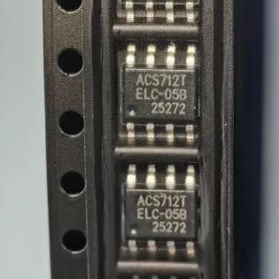
Image for reference only

Manufacturer Part:

ACS712ELCTR-05B-T

Package:

SOIC-8 (LC) (4.9 x 3.9 mm, 1.27mm pitch)

Brand:
Product Categories:
Other recommendations you may be interested in.
Description

The ACS712ELCTR-05B-T from Allegro MicroSystems is a galvanically isolated Hall-effect linear current sensor IC with plus or minus 5 A measurement range in an 8-pin SOIC (LC) package. Key specifications: total output error 1.5 percent at 25 degrees C; 185 mV/A output sensitivity; 5 V single supply operation; 80 kHz bandwidth with filter pin; 5 us output rise time in response to step input current; 1.2 mOhm internal conductor resistance; 2.1 kV RMS minimum isolation voltage from pins 1-4 to pins 5-8; ratiometric output from supply voltage (output voltage proportional to VCC); factory-trimmed for accuracy; extremely stable output offset voltage; nearly zero magnetic hysteresis; output voltage 2.5 V at zero current (VCC/2); low-noise analog signal path; FILTER pin allows external bandwidth adjustment; operating temperature -40 to +85 degrees C. The ELC package (SOIC-8) with TR suffix denotes tape and reel packaging. 100 percent matte tin leadframe for Pb-free assembly. UL recognized component (file E316429).

The ACS712ELCTR-05B-T from Allegro MicroSystems is a fully integrated Hall-effect current sensor that provides galvanically isolated, linear current measurement in a compact SOIC-8 package. The device uses Allegro’s patented Hall-effect technology to measure AC or DC current through an internal conductor, providing a voltage output proportional to the current with 2.1 kV RMS galvanic isolation between the current-carrying pins and the sensor electronics.

The ACS712 is one of the most widely used current sensors in the hobbyist and maker communities, as well as in industrial and automotive applications. Its simplicity of use (5 V supply, analog voltage output) and low cost have made it the de facto standard for non-invasive current measurement in Arduino and Raspberry Pi projects.

The 05B variant is the most sensitive version, with a measurement range of plus or minus 5 A and a sensitivity of 185 mV/A. Other variants in the ACS712 family include the 20A version (ELCTR-20A-T, 100 mV/A) and the 30A version (ELCTR-30A-T, 66 mV/A). The trade-off is between measurement range and resolution: the 05B version provides the finest resolution (smallest detectable current) but the narrowest range, while the 30A version provides the widest range but the coarsest resolution.

The galvanic isolation is a critical safety feature. The current-carrying conductor (IP+ to IP-) is electrically isolated from the sensor electronics (VCC, GND, VIOUT, FILTER) by the Hall-effect IC’s monolithic construction. The 2.1 kV RMS isolation rating allows the sensor to measure high-voltage circuits (up to 2.1 kV RMS above the sensor supply ground) safely, without any direct electrical connection. This is essential for measuring mains-powered loads, motor drives, and other high-voltage applications.

The ratiometric output means that the output voltage is proportional to the supply voltage (VCC). At zero current, the output is VCC/2 (2.5 V with a 5 V supply). At plus 5 A, the output is VCC/2 + 5 A x 185 mV/A = 2.5 V + 0.925 V = 3.425 V. At minus 5 A, the output is 2.5 V – 0.925 V = 1.575 V. This ratiometric architecture means that any noise on the VCC supply appears proportionally on the output, which can be cancelled by using VCC as the ADC reference voltage.

The 1.2 mOhm internal conductor resistance is extremely low, resulting in minimal power dissipation and voltage drop even at full-scale current. At 5 A, the power dissipation is only I squared x R = 25 x 0.0012 = 30 mW, and the voltage drop is only 6 mV. This makes the ACS712 suitable for measuring current in high-efficiency power circuits where insertion loss must be minimized.

The FILTER pin is a unique feature that allows the user to adjust the sensor bandwidth and noise performance by connecting an external capacitor from FILTER to GND. The bandwidth is approximately 80 kHz with no capacitor. Adding a capacitor reduces the bandwidth (and noise) according to the formula: Bandwidth = 1 / (2 x pi x 1 kOhm x CFILTER). For a 1 nF capacitor, the bandwidth is approximately 160 kHz (increased filtering). This allows the designer to trade response speed for noise reduction based on the application requirements.

The ELC package (SOIC-8) provides a compact, surface-mount solution. The TR suffix indicates tape and reel packaging for automated assembly. The 100 percent matte tin leadframe is compatible with lead-free soldering processes.

The ACS712ELCTR-05B-T operates as a Hall-effect linear current sensor using Allegro’s monolithic integration of a Hall element, signal conditioning, and current conductor.

Hall Effect Principle: When a current-carrying conductor (the IP+ to IP- path inside the IC) generates a magnetic field proportional to the current, a Hall element positioned adjacent to the conductor detects this magnetic field. The Hall voltage produced is proportional to the product of the magnetic flux density and the bias current through the Hall element. Since the magnetic flux density is proportional to the current being measured, the Hall voltage is directly proportional to the measured current.

Internal Conductor Path: The current to be measured flows through the IP+ pin (pins 1-2) to the IP- pin (pins 3-4) through an internal copper conductor integrated into the IC package. This conductor has a resistance of only 1.2 mOhm, minimizing power dissipation and voltage drop. The conductor is positioned directly above the Hall element, ensuring strong magnetic coupling and high sensitivity.

Signal Conditioning: The raw Hall voltage is processed through several stages of analog signal conditioning: (1) a high-gain amplifier boosts the small Hall voltage; (2) a chopper-stabilized offset cancellation circuit removes the DC offset and drift of the Hall element; (3) a factory-trimmed calibration circuit adjusts the gain and offset for the specified sensitivity (185 mV/A) and zero-current output (VCC/2); (4) the output buffer drives the VIOUT pin with a low-impedance voltage output.

Ratiometric Architecture: The output voltage is ratiometric to the supply voltage (VCC). This means that the zero-current output is always VCC/2, and the sensitivity scales with VCC. If VCC is 5.0 V, the sensitivity is 185 mV/A; if VCC is 4.5 V, the sensitivity scales to approximately 185 x 4.5/5.0 = 166.5 mV/A. To eliminate the effect of VCC variation on the measurement, the ADC that reads the VIOUT pin should use VCC as its reference voltage, so that both the sensor output and the ADC reference scale together.

FILTER Pin Operation: The FILTER pin provides access to an internal node in the signal path where an external capacitor can be connected to GND to create a low-pass filter. The internal resistance at this node is approximately 1 kOhm. The filter bandwidth is BW = 1 / (2 x pi x 1 kOhm x CFILTER). With no external capacitor, the bandwidth is limited by internal compensation to approximately 80 kHz. Adding CFILTER reduces the bandwidth and the output noise. This is useful for DC and low-frequency current measurement where noise must be minimized.

Galvanic Isolation: The current-carrying conductor (pins 1-4) and the sensor electronics (pins 5-8) are separated by the IC’s monolithic isolation barrier. The isolation barrier is designed to withstand 2.1 kV RMS (60 Hz, 1 minute) between the two domains. This isolation is achieved through the IC’s construction, where the conductor and the Hall element are separated by an insulating layer within the silicon die. No external optocouplers or isolation amplifiers are required.

Magnetic Hysteresis: The Hall element and the magnetic circuit are designed for nearly zero magnetic hysteresis. This means that the sensor output does not depend on the previous current history, ensuring accurate and repeatable measurements regardless of whether the current has been high or low before the measurement.

Pin Name Type Description
1 IP+ Conductor Positive current conductor input; the current to be measured enters through this pin and the adjacent pin 2; these two pins are internally connected; the conductor resistance from IP+ to IP- is 1.2 mOhm; for PCB layout, connect both pins 1 and 2 to the current trace to ensure full current flows through the internal conductor
2 IP+ Conductor Positive current conductor input (parallel connection with pin 1); connect both pins 1 and 2 together on the PCB; the wide internal conductor handles up to 5 A continuous current with minimal heating
3 IP- Conductor Negative current conductor output; the measured current exits through this pin and pin 4; these two pins are internally connected; connect both pins 3 and 4 together on the PCB
4 IP- Conductor Negative current conductor output (parallel connection with pin 3); the combined IP+ and IP- pins form the isolated current path; there is no electrical connection between pins 1-4 and pins 5-8
5 GND Ground Sensor ground; connect to the PCB ground plane; this ground is electrically isolated from the IP+ and IP- conductor path; bypass VCC to GND with a 100 nF ceramic capacitor close to the pins
6 FILTER Analog External filter capacitor connection; connect a capacitor from FILTER to GND to reduce output noise and bandwidth; bandwidth = 1 / (2 x pi x 1 kOhm x CFILTER); with no capacitor, bandwidth is approximately 80 kHz; for DC measurement, a 1 nF capacitor gives approximately 160 kHz bandwidth; for 50/60 Hz measurement, larger capacitors reduce high-frequency noise
7 VIOUT Output Analog output voltage proportional to the measured current; ratiometric to VCC; at zero current, VIOUT = VCC/2 (2.5 V with 5 V supply); at plus 5 A, VIOUT = VCC/2 + 5 x 0.185 = 3.425 V; at minus 5 A, VIOUT = VCC/2 – 0.925 = 1.575 V; output impedance is low enough to drive most ADC inputs directly; connect to MCU ADC input
8 VCC Power Positive supply voltage; 5.0 V nominal (4.5 to 5.5 V); the output sensitivity and zero-current offset are ratiometric to VCC; for best accuracy, use VCC as the ADC reference voltage so that VCC variations cancel out; bypass with 100 nF ceramic capacitor to GND close to the pin; typical supply current is 10 mA
Application Description
Motor Current Monitoring Measure DC motor current for torque estimation, stall detection, and overcurrent protection; 5 A range covers small to medium motors; 80 kHz bandwidth captures motor current ripple; galvanic isolation measures high-side motor current safely; FILTER pin reduces PWM switching noise; output connects directly to MCU ADC for current readout
Battery Charge/Discharge Monitor Measure Li-ion battery charge and discharge current in power banks, UPS, and EV BMS; bidirectional measurement (positive and negative current) tracks both charge and discharge; 1.2 mOhm insertion loss preserves battery efficiency; ratiometric output compatible with 5 V ADC; 5 A range suits single-cell to multi-cell packs
Solar Panel Current Sensing Monitor photovoltaic panel output current for maximum power point tracking (MPPT); galvanic isolation measures panel current at high voltage potential; low insertion loss minimizes power waste; FILTER pin smooths variable solar output for averaging; 5 A range covers typical residential panel strings
Power Supply Overcurrent Protection Measure output current of 5 V or 3.3 V power supply rails; analog output feeds MCU comparator or ADC for software overcurrent detection; faster than fuse-based protection; 5 us response time enables rapid shutdown; FILTER pin sets appropriate response time vs. noise trade-off
Home Automation Energy Monitor Measure AC mains current (with burden resistor and rectification) for energy monitoring; galvanic isolation ensures safety when measuring mains-connected loads; Arduino-compatible with simple analog input reading; popular in DIY smart home energy monitoring projects
Model Manufacturer Compatibility Key Difference
ACS712ELCTR-20A-T Allegro Same Family, Wider Range Plus or minus 20 A measurement range; 100 mV/A sensitivity (lower); same SOIC-8 package and pinout; same 5 V supply and isolation; use when 5 A range is insufficient; trade-off: lower resolution per amp
ACS712ELCTR-30A-T Allegro Same Family, Widest Range Plus or minus 30 A measurement range; 66 mV/A sensitivity (lowest); same SOIC-8 package and pinout; use for high-current applications; lowest resolution of the ACS712 family
ACS723LLCTR-05AB-T Allegro Same Package, Improved Next-generation 5 A current sensor; improved accuracy (1 percent total error); higher bandwidth (100 kHz); lower noise; same SOIC-8 pinout; recommended for new designs; drop-in upgrade
INA219BIDR TI Different Architecture Shunt-based current sensor with I2C interface; measures current via external shunt resistor; plus or minus 3.2 A range; 12-bit ADC integrated; no galvanic isolation; digital output; use when I2C interface preferred and isolation not required
CT (Current Transformer) Various Alternative Technology Non-invasive AC-only current measurement; measures current via magnetic coupling; inherently isolated; no supply voltage needed; AC only (no DC measurement); use for mains AC current monitoring where DC measurement is not needed
Recommend Parts
8-bit AVR MCU, 20MHz, 32KB Flash, 2KB SRAM, TQFP-32, NRND

Brand:

Package:

TQFP-32 (7×7×1.05 mm)
In stock:
13010pcs

Cargo cycle: 3~7 Days
The minimum order is 1

Go to Inquiry
E1/T1 Line Interface Unit, 8.192Mbps, short/long haul, integrated CDR, 80-MQFP, 3.3V

Brand:

Package:

80-MQFP (14x14mm)
In stock:
14099pcs

Cargo cycle: 3~7 Days
The minimum order is 1

Go to Inquiry
ARM7TDMI MCU, 55MHz, 256KB Flash, 64KB SRAM, Ethernet MAC, USB, CAN, LQFP-100

Brand:

Package:

LQFP-100
In stock:
3752pcs

Cargo cycle: 3~7 Days
The minimum order is 1

Go to Inquiry
3A adjustable LDO, 1.24-15V output, 450mV dropout, TO-263-5, fast transient response

Brand:

Package:

TO-263-5 (10.67 x 9.17 x 4.6 mm)
In stock:
7577pcs

Cargo cycle: 3~7 Days
The minimum order is 1

Go to Inquiry
12-bit single-channel voltage DAC, SPI, rail-to-rail output, 2.7-5.5V, SOIC-8, AEC-Q100

Brand:

Package:

SOIC-8 (4.9 x 3.9 mm)
In stock:
2849pcs

Cargo cycle: 3~7 Days
The minimum order is 1

Go to Inquiry
8-bit AVR MCU, 32KB Flash, 2KB SRAM, 23 I/O, 8ch 10-bit ADC, TQFP-32, T&R

Brand:

Package:

TQFP-32 (7.0 x 7.0 x 1.05mm)
In stock:
6946pcs

Cargo cycle: 3~7 Days
The minimum order is 1

Go to Inquiry
Quality Assurance

All electronic components we source from our partnered supply chains go through strict incoming inspections.Through careful testing, we ensure everything delivered to customers is genuine original parts and meets quality requirements.In addition, we keep complete inspection records to make the entire supply chain process clear and traceable.

Certification
We have obtained a number of professional certifications and built our own professional testing laboratory.This ensures that every product we deliver to our customers meets the highest quality requirements.We conduct tests in strict accordance with procedures to ensure stable product quality and accurate parameters.To guarantee genuine original parts, we also cooperate with reliable third-party testing institutions for strict quality inspection.We always attach great importance to quality and fully comply with industry standards, relevant regulations, and ISO 9001:2015 requirements.

Shipping & Payment

All electronic components we source from our partnered supply chains go through strict incoming inspections.Through careful testing, we ensure everything delivered to customers is genuine original parts and meets quality requirements.In addition, we keep complete inspection records to make the entire supply chain process clear and traceable.

Certification
We have obtained a number of professional certifications and built our own professional testing laboratory.This ensures that every product we deliver to our customers meets the highest quality requirements.We conduct tests in strict accordance with procedures to ensure stable product quality and accurate parameters.To guarantee genuine original parts, we also cooperate with reliable third-party testing institutions for strict quality inspection.We always attach great importance to quality and fully comply with industry standards, relevant regulations, and ISO 9001:2015 requirements.

Service & Packaging

All electronic components we source from our partnered supply chains go through strict incoming inspections.Through careful testing, we ensure everything delivered to customers is genuine original parts and meets quality requirements.In addition, we keep complete inspection records to make the entire supply chain process clear and traceable.

Certification
We have obtained a number of professional certifications and built our own professional testing laboratory.This ensures that every product we deliver to our customers meets the highest quality requirements.We conduct tests in strict accordance with procedures to ensure stable product quality and accurate parameters.To guarantee genuine original parts, we also cooperate with reliable third-party testing institutions for strict quality inspection.We always attach great importance to quality and fully comply with industry standards, relevant regulations, and ISO 9001:2015 requirements.









