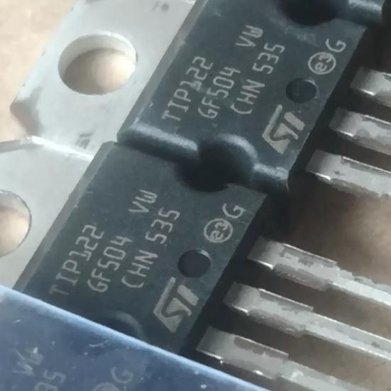
The TIP122 operates as a Darlington pair NPN power transistor with integrated base-emitter shunt resistors.
Darlington Pair Configuration: The device integrates two NPN transistors (Q1 and Q2) on a single monolithic die. Q1 is the input or driver transistor, and Q2 is the output or power transistor. The emitter of Q1 connects directly to the base of Q2, and the collectors of both transistors connect together to form the external collector terminal. When base current IB flows into the base of Q1, Q1 amplifies it by its current gain hFE1, producing an emitter current of hFE1 x IB. This emitter current becomes the base current of Q2, which Q2 further amplifies by hFE2, producing a collector current of hFE2 x (hFE1 x IB). The total collector current is approximately (hFE1 x hFE2) x IB, giving the Darlington pair an overall current gain of hFE_total = hFE1 x hFE2, typically 1000 or more.
Current Flow: In the active or saturated state, conventional current flows from collector to emitter (for NPN), with the magnitude controlled by the base current. For a load connected between the collector and the positive supply (low-side switch configuration), when the base is driven with sufficient current, the transistor saturates and the load current flows from the supply through the load and the transistor to ground. The minimum base current required to maintain saturation at a given collector current is IB(min) = IC / hFE. For IC=3A and hFE=1000, IB(min) = 3mA. In practice, a base current 1.5x to 2x the minimum is used (overdrive factor) to ensure deep saturation and minimum VCE(sat).
Base-Emitter Shunt Resistors: Two internal resistors are connected across the base-emitter junctions of Q1 and Q2. These resistors provide:
(1) Turn-off acceleration: When the external base drive is removed, the stored charge in the base-emitter junctions must be dissipated before the transistor can turn off. The shunt resistors provide a discharge path for this stored charge, speeding up the turn-off transition. Without these resistors, the turn-off time would be significantly longer.
(2) Leakage current management: At high temperatures, the collector-base leakage current (ICBO) of each transistor increases exponentially. In a Darlington pair, the leakage current of Q1 is amplified by Q2, potentially causing false turn-on. The shunt resistors divert this leakage current away from the base-emitter junctions, preventing unwanted conduction.
VCE(sat) Characteristics: The saturation voltage of a Darlington pair is higher than a single transistor because VCE(sat) = VBE2 + VCE1(sat), where VBE2 is the base-emitter voltage of Q2 (approximately 0.7-1.2V when conducting) and VCE1(sat) is the collector-emitter saturation voltage of Q1 (approximately 0.3-0.7V in saturation). The total VCE(sat) is therefore at least 1.0-1.9V even at low currents, and can reach 4.0V at IC=5A. This is a fundamental characteristic of the Darlington configuration and is the primary trade-off for the high current gain.
Thermal Considerations: The power dissipated in the transistor is P = VCE x IC. In the saturated (switching) state, most of the dissipation comes from VCE(sat) x IC (conduction loss). During switching transitions, additional dissipation occurs (switching loss) as the transistor passes through the linear region where both VCE and IC are significant. For low-frequency switching (below 1kHz), switching losses are negligible and the total dissipation is dominated by conduction loss. The thermal design must ensure that the junction temperature remains below 150C under worst-case conditions, which typically requires a heatsink rated for the expected power dissipation.
Safe Operating Area (SOA): The TIP122 has a defined safe operating area that specifies the maximum allowable VCE-IC combinations at various pulse durations. For DC operation, the SOA is limited by the maximum power dissipation hyperbola (IC = Pmax/VCE). For short pulses, higher VCE-IC combinations are allowed. The device also has a secondary breakdown limit that further restricts the high-voltage, high-current region of the SOA. Operating within the SOA at all times is essential for reliable device operation.





 English
  简体中文
简体中文  Español
  العربية




