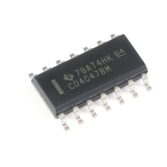
The CD4047BM operates as a versatile CMOS timing circuit configurable for monostable or astable operation using a single external resistor-capacitor network.
Internal Architecture: The device contains a flip-flop, timing logic, trigger logic, and output buffers. The timing element is the external RC network connected between the R-C COMMON pin and the TIMING R and TIMING C pins. The internal circuit charges and discharges the external capacitor through the external resistor, with the timing period determined by the RC time constant and an internal scaling factor derived from the CMOS switching thresholds.
Monostable Mode: In monostable (one-shot) mode, the device generates a single output pulse of defined width when triggered. The positive output (Q) pulse width is T = 2.48 x R x C, and the complementary output (Q-bar) pulse width is T = 1.24 x R x C. The factor of 2 difference arises because the Q output is high for the full timing cycle while Q-bar is low for the full cycle (the timing reference point differs). The device can be triggered by a positive edge on +TRIGGER or a negative edge on -TRIGGER. After triggering, the output pulse is independent of further trigger inputs unless the RETRIGGER input is used. The retrigger function allows the output pulse to be extended: if a retrigger pulse arrives before the current timing cycle completes, a new timing cycle starts from that point, extending the total output pulse duration. The external reset (MR, active high) immediately terminates the output pulse and resets the timing circuit regardless of the current state.
Astable Mode: In astable (free-running) mode, the device oscillates continuously, generating a square wave output with approximately 50% duty cycle. The oscillation period is T = 4.40 x R x C, giving a frequency of f = 1/(4.40RC). The ASTABLE input must be held high to enable oscillation. Both Q and Q-bar provide complementary square wave outputs. The astable mode can be gated by controlling the ASTABLE input, allowing the oscillation to be started and stopped under external logic control. The 50% duty cycle is inherent in the symmetric charge/discharge cycle of the RC network through the internal CMOS switches.
Timing Accuracy: The timing accuracy depends on the tolerance and stability of the external R and C components. Typical accuracy is within 1-2% at 25°C with precision components. Temperature drift is determined primarily by the external components and the internal CMOS threshold voltage temperature coefficient. For best accuracy, low-temperature-coefficient resistors (metal film) and capacitors (NPO/COG ceramic or film) are recommended. The internal scaling factors (2.48 and 4.40) account for the ratio of CMOS switching thresholds to the supply voltage.
Power Supply and Noise Immunity: The wide 3V to 18V supply range makes the device compatible with both 5V logic and higher-voltage industrial systems. The CMOS technology provides wide noise immunity (45% of VDD typical), making the timing circuit resistant to noise-induced false triggering. The very low static power consumption (sub-microampere) means the device adds negligible load to the power supply when not actively timing.





 English
  简体中文
简体中文  Español
  العربية




