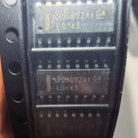
The SN74LS145DR operates as a combinational logic circuit that decodes a 4-bit BCD input into one of ten active-low output signals, using a network of inverters and NAND gates followed by NPN output transistors.
Input Logic: The four BCD input lines (A, B, C, D) represent a decimal digit from 0 to 9. Input A is the least significant bit (LSB) and D is the most significant bit (MSB). The input coding follows standard BCD: 0000 = 0, 0001 = 1, 0010 = 2, …, 1001 = 9. Input codes 1010 through 1111 (decimal 10-15) are invalid BCD values and result in all outputs being OFF.
Decoding Logic: The device consists of eight inverters and ten four-input NAND gates. The four BCD inputs and their complements (generated by the inverter pairs) are connected to the NAND gates in a pattern that implements the BCD decoding truth table. Each NAND gate corresponds to one decimal output (0 through 9) and is wired to activate only when the BCD input matches the corresponding decimal value. For example, the NAND gate for output 0 receives inputs A-complement, B-complement, C-complement, and D-complement, so it activates only when all inputs are LOW (BCD 0000).
Invalid BCD Handling: The NAND gate wiring inherently ensures that none of the ten NAND gates activates for input codes 1010 through 1111. This is because each output NAND gate requires a specific combination of true and complemented inputs that only matches a valid BCD value (0-9). For example, output 0 requires D=0, which is not satisfied for any code 1010-1111 (where D=1). Similarly, outputs 8 and 9 require D=1 with specific ABC patterns that do not match the invalid codes. This full decoding of valid input logic ensures that all outputs are OFF for invalid inputs, providing natural blanking.
Output Stage: Each of the ten outputs is an NPN transistor with an open-collector configuration. When the corresponding NAND gate output is LOW (the selected output), the NAND gate drives the base of the NPN transistor through a current-limiting resistor, turning the transistor ON. The transistor saturates, pulling the output pin LOW (close to GND) and sinking current through the load connected between a positive supply and the output pin. When the NAND gate output is HIGH (unselected outputs), the NPN transistor is OFF and the output pin is effectively open-circuited (high impedance), allowing the load to be pulled to the external supply voltage through the load itself.
Current Drive: Each output transistor can sink up to 80 mA of continuous current. The transistor is designed with a saturated collector-emitter voltage (VCE(sat)) of approximately 0.7 V at 80 mA, so the voltage drop across the output transistor is relatively small even at maximum current. The output breakdown voltage (VCE(off)) is 15 V minimum, meaning the output can be connected to loads powered by up to 15 V when the transistor is OFF.
Power Dissipation: The LS variant uses Schottky-clamped transistors in the internal logic gates, which prevents the transistors from entering deep saturation and reduces storage time. This results in a typical power dissipation of only 35 mW, compared to 215 mW for the standard TTL 74145 variant. The lower power dissipation also reduces the junction temperature rise, improving reliability in multi-IC applications.
TTL Input Characteristics: The inputs are standard LS TTL, requiring 0.4 mA sink current at LOW level (0.8 V maximum) and negligible current at HIGH level (20 uA at 2.7 V minimum). One LS TTL input represents one unit load, so the 74LS145 inputs can be driven by any standard LS TTL output. The inputs are also compatible with CMOS logic (74HC, 74HCT) when appropriate pull-up resistors are used to ensure the HIGH level exceeds the 2 V minimum TTL threshold.





 English
  简体中文
简体中文  Español
  العربية