首页 > 集成电路 IC > ST485EBDR

ST485EBDR


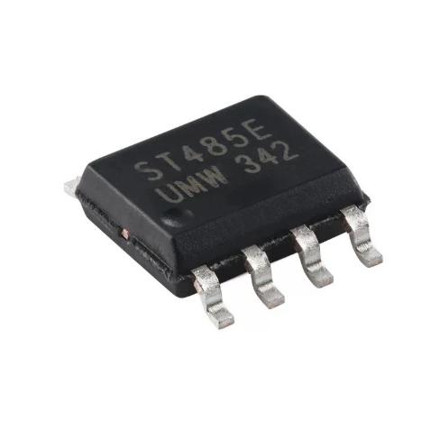
RS-485/RS-422 收发器,5V,半双工,256 节点,30ns prop 延迟,+/-15kV ESD,300uA Iq,SO-8,-40~85C,磁带和卷盘

50000

有效库存
转到查询

Image for reference only

制造商零件:

ST485EBDR

包装:

SO-8(5.0 x 6.0 毫米,1.27 毫米间距)

品牌:
产品类别:
您可能感兴趣的其他建议.
说明

The ST485EBDR from STMicroelectronics is a low-power RS-485/RS-422 transceiver with plus or minus 15 kV ESD protection (HBM) and plus or minus 8 kV IEC-1000-4-2 contact discharge protection, in an SO-8 package. Key specifications: single 5 V supply; half-duplex configuration with one driver and one receiver; allows up to 256 transceivers on the bus; 30 ns propagation delay with 5 ns skew; low quiescent current 300 uA typical; -7 V to +12 V common-mode input voltage range; 70 mV typical input hysteresis; driver short-circuit current limiting with thermal shutdown; driver maintains high impedance in 3-state or with power off; designed for bidirectional data communications on multipoint bus transmission lines. Operating temperature -40 to +85 degrees C. SO-8 package with tape and reel packaging (DR suffix). Ecopack3, EAR99, budgetary price $0.53 at 1K units.

The ST485EBDR from STMicroelectronics is an industry-standard RS-485/RS-422 transceiver designed for half-duplex differential data communication on multipoint bus transmission lines. It is part of the ST485E family, which adds enhanced ESD protection to the classic ST485 design, making it suitable for industrial environments where electrostatic discharge events are common.

The ST485EBDR implements a single driver and a single receiver in a half-duplex configuration, meaning the driver and receiver share the same differential bus pins (A and B). The direction of data flow is controlled by the RE (receiver enable) and DE (driver enable) pins. This is the most common configuration for RS-485 applications, where data flows in one direction at a time.

The ESD protection is a key differentiator of the ST485E series. The plus or minus 15 kV Human Body Model (HBM) rating and plus or minus 8 kV IEC 1000-4-2 contact discharge rating provide robust protection against electrostatic discharge events that can occur during cable handling, connector mating, or in harsh industrial environments. This level of ESD protection eliminates the need for external TVS diodes on the bus pins in many applications, reducing BOM cost and board space.

The 256-transceiver bus loading capability means that up to 256 ST485EBDR devices can share a single RS-485 bus without signal integrity degradation. This is achieved by the unit load (UL) specification: the ST485EBDR presents 1/4 unit load to the bus, while the RS-485 standard allows a maximum of 32 unit loads. At 1/4 unit load, 32 / 0.25 = 128 devices can be connected; with the extended common-mode range and low input current, up to 256 devices are possible in practice.

The 30 ns propagation delay and 5 ns skew are well-suited for data rates up to 10 Mbps, which covers virtually all RS-485 applications including high-speed Modbus, Profibus, and custom protocols. The low skew (difference between propagation delays) ensures minimal timing jitter and reliable clock recovery.

The 300 uA quiescent current makes the ST485EBDR suitable for battery-powered and low-power applications. In standby mode (driver disabled), the device draws only 300 uA from the 5 V supply, which is significantly less than many competing transceivers that draw 1-3 mA.

The thermal shutdown protection is an important safety feature. If the driver output is shorted to another driver output (a common bus fault condition), the driver current limiting activates first. If the sustained power dissipation causes the junction temperature to exceed the thermal shutdown threshold (approximately 150 degrees C), the driver outputs are forced to high impedance, preventing device damage. The driver automatically recovers when the junction temperature drops below the threshold.

The DR suffix indicates SO-8 package with tape and reel packaging, suitable for automated SMT assembly. The device is also available in DIP-8 (ST485EBPT) for through-hole prototyping.

The ST485EBDR operates as a differential RS-485/RS-422 transceiver in half-duplex mode, converting between single-ended TTL/CMOS logic levels and differential RS-485 bus signals.

Driver Operation: The driver takes a single-ended TTL/CMOS input at the DI (Data Input) pin and converts it to a differential output on the A and B bus pins. When DI is high, the driver forces A higher than B (logic 1); when DI is low, the driver forces B higher than A (logic 0). The driver output voltage swing is typically 2 V differential with a 54 Ohm load (simulating a terminated bus with two 120 Ohm termination resistors). The DE (Driver Enable) pin controls the driver output state: when DE is high, the driver is active; when DE is low, the driver outputs are high impedance (3-state), effectively disconnecting the driver from the bus.

Receiver Operation: The receiver monitors the differential voltage between the A and B bus pins. If V(A) – V(B) exceeds plus 200 mV, the receiver output RO (Receiver Output) is high; if V(A) – V(B) is less than -200 mV, the output is low. The 70 mV typical input hysteresis provides noise immunity by requiring the differential voltage to cross two separate thresholds (one for high-to-low transition and one for low-to-high transition), preventing output oscillation when the input is near the switching threshold. The RE (Receiver Enable) pin controls the receiver: when RE is low, the receiver is active; when RE is high, the receiver output is high impedance.

Half-Duplex Control: In half-duplex operation, the driver and receiver share the same A and B bus pins. The DE and RE pins are typically tied together so that the device is either transmitting (DE high, RE high) or receiving (DE low, RE low). This prevents the driver from conflicting with received signals on the shared bus. When DE is low and RE is low, only the receiver is active, and the driver outputs are high impedance, allowing other transceivers on the bus to drive the A and B lines.

ESD Protection Structure: Each driver output and receiver input pin (A and B) includes ESD protection clamps rated for plus or minus 15 kV HBM and plus or minus 8 kV IEC contact discharge. These clamps are designed to shunt high-voltage, short-duration ESD events to the supply rails without latch-up. The ESD structures are transparent during normal operation and do not affect the RS-485 signal integrity.

Thermal Shutdown: The driver includes a thermal shutdown circuit that monitors the junction temperature. When the junction temperature exceeds approximately 150 degrees C (typically caused by a sustained short-circuit on the bus), the driver outputs are forced to high impedance, preventing further power dissipation. The driver automatically recovers when the junction temperature drops below the thermal shutdown threshold by approximately 20 degrees C.

Bus Fail-Safe: The ST485EBDR requires external fail-safe biasing resistors to ensure a known logic state on the bus when all drivers are disabled (bus idle). ST application note AN1690 provides detailed guidance on fail-safe biasing values. Typically, a pull-up resistor on the A line to VCC and a pull-down resistor on the B line to GND ensure that the receiver output is high (logic 1) when the bus is idle.

针脚 名称 类型 说明
1 RO 输出 Receiver output; TTL/CMOS compatible; when the receiver is enabled (RE low) and the differential input V(A)-V(B) exceeds plus 200 mV, RO is high; when V(A)-V(B) is less than -200 mV, RO is low; when RE is high, RO is high impedance; the 70 mV input hysteresis prevents output chatter near the threshold
2 RE 输入 Receiver enable; active low; when RE is low (below 0.8 V), the receiver is active and drives RO based on the bus state; when RE is high (above 2.0 V), the receiver output RO is high impedance; typically tied to DE for half-duplex operation so that the device either transmits or receives but not both simultaneously
3 可选择丢弃 输入 Driver enable; active high; when DE is high (above 2.0 V), the driver is active and drives the A/B outputs based on the DI input; when DE is low (below 0.8 V), the driver outputs A and B are high impedance (3-state), disconnecting the driver from the bus; typically tied to RE for half-duplex operation
4 DI 输入 Driver data input; TTL/CMOS compatible; when the driver is enabled (DE high), a high on DI forces A above B (logic 1) and a low on DI forces B above A (logic 0); when the driver is disabled (DE low), DI is ignored; this pin has no effect when DE is low
5 接地 地面 Ground connection; connect to the PCB ground plane; all signal and ESD return paths reference this pin; for best signal integrity, use a solid ground plane under the device and keep GND connections short
6 A I/O (Bus) Non-inverting driver output / receiver input; connects to the RS-485 bus through the PCB trace and cable; ESD protected to plus or minus 15 kV HBM; in half-duplex mode, this pin is shared by the driver output and receiver input; connect to the A bus line with a 120 Ohm termination resistor at each end of the bus
7 B I/O (Bus) Inverting driver output / receiver input; connects to the RS-485 bus; ESD protected to plus or minus 15 kV HBM; in half-duplex mode, this pin is shared by the driver output and receiver input; connect to the B bus line with a 120 Ohm termination resistor at each end of the bus; fail-safe biasing: pull-up A to VCC and pull-down B to GND
8 VCC 电源 Positive supply voltage; 5 V nominal (4.75 V to 5.25 V); bypass with 100 nF ceramic capacitor to GND close to the pin; the supply current depends on the operating mode: 300 uA typical quiescent (driver disabled), higher when actively driving the bus
应用 说明
Modbus RTU Industrial Network RS-485 physical layer for Modbus RTU communication between PLCs, sensors, and actuators; up to 256 nodes on a single bus; 10 Mbps data rate supports high-speed polling; ESD protection critical for field wiring; 120 Ohm termination at each bus end; fail-safe biasing ensures defined idle state; thermal shutdown protects against wiring faults
Building Automation (BACnet MS/TP) RS-485 bus for HVAC controllers, lighting, and access control; half-duplex operation matches MS/TP protocol; low 300 uA quiescent current suitable for battery-backed nodes; ESD protection for long cable runs between floors; 256-node capacity supports large building networks
Electric Meter (e-Meter) Communication RS-485 data link for smart metering systems; ST application note AN1702 details e-meter design; ESD protection essential for outdoor meter installations; low power consumption extends battery life for power-outage data retention; 30 ns propagation delay supports high-speed meter reading
Motor Drive Communication RS-485 link between motor controller and supervisory system; ESD and thermal protection withstand industrial noise and wiring faults; half-duplex mode for command/response protocol; 120 Ohm termination prevents signal reflections on long cables; wide common-mode range tolerates ground potential differences
Security and Access Control RS-485 bus connecting card readers, keypads, and door controllers; ESD protection for frequently handled reader devices; up to 256 nodes per bus segment; low quiescent current for standby power budgets; fail-safe biasing ensures reliable communication during idle periods
模型 制造商 兼容性 主要区别
ST485EBPT ST Same Device, DIP Package Same ST485EB in DIP-8 through-hole package; tube packaging; identical electrical specifications; use for prototyping or low-volume production requiring socket mounting
SN75176BDR TI 针脚兼容替代方案 Industry-standard RS-485 transceiver in SO-8; pin-compatible with ST485EBDR; similar specifications; 60 ns propagation delay (slower); lower ESD rating; widely available; use as second-source alternative
MAX485ECSA 模拟器件公司 针脚兼容替代方案 RS-485 transceiver in SO-8; pin-compatible; plus or minus 15 kV ESD; 2.5 Mbps data rate (slower); lower quiescent current (120 uA); use when lower power is needed and 2.5 Mbps is sufficient
SP3485EN MaxLinear Pin-Compatible, 3.3V 3.3 V RS-485 transceiver in SO-8; pin-compatible; lower supply voltage; 10 Mbps; use when 3.3 V supply is preferred over 5 V
THVD1550DR TI Higher Speed, Better ESD RS-485 transceiver in SO-8; 50 Mbps data rate; plus or minus 18 kV IEC ESD; wider common-mode range (-20 V to +25 V); not pin-compatible; use for new designs needing higher speed or better ruggedness
推荐部件
Cortex-M0+ ultra-low-power MCU, 32MHz, 128KB Flash, crystal-less USB, LQFP-64

品牌:

封装:

LQFP-64 (10×10 mm)
有库存:
14446pcs

货运周期:3~7 天
最低订购量为 1

转到查询
Cortex-M4F MCU, 168MHz, 512KB Flash, 192KB SRAM, Ethernet, USB OTG, LQFP-100

品牌:

封装:

LQFP-100 (14×14×1.4 mm)
有库存:
2870pcs

货运周期:3~7 天
最低订购量为 1

转到查询
ARM Cortex-M4F MCU, 72MHz, 384KB Flash, 64KB SRAM, dual ADC, 4 comparators, 2 op amps, LQFP-100

品牌:

封装:

LQFP-100 (14 x 14 x 1.4 mm)
有库存:
12274pcs

货运周期:3~7 天
最低订购量为 1

转到查询
ARM Cortex-M4F MCU, 168MHz, 1MB Flash, 192KB SRAM, Ethernet, USB OTG HS, UFBGA-176

品牌:

封装:

UFBGA-176 (10 x 10 mm, 0.65mm pitch)
有库存:
9303pcs

货运周期:3~7 天
最低订购量为 1

转到查询
Quad JFET-input op amp, 4MHz GBP, 16V/µs slew rate, 200pA bias current, SOIC-14

品牌:

封装:

SOIC-14 (8.75 x 4 x 1.65 mm)
有库存:
9834pcs

货运周期:3~7 天
最低订购量为 1

转到查询
Ultra-low-power Cortex-M3 MCU, 32MHz, 256KB Flash, 32KB SRAM, LCD controller, LQFP-64

品牌:

封装:

LQFP-64 (10x10mm)
有库存:
5417pcs

货运周期:3~7 天
最低订购量为 1

转到查询
质量保证

我们从合作供应链采购的所有电子元件都经过严格的进货检验。通过仔细的测试,我们确保交付给客户的所有产品都是原装正品,符合质量要求。此外,我们还保存完整的检验记录,使整个供应链流程清晰可查。.

认证
我们获得了多项专业认证,并建立了自己的专业检测实验室,确保交付给客户的每一件产品都符合最高质量要求。我们严格按照流程进行检测,确保产品质量稳定、参数准确。为保证原装正品,我们还与可靠的第三方检测机构合作,进行严格的质量检测。我们始终高度重视质量,完全符合行业标准、相关法规和 ISO 9001:2015 的要求。.

发货与付款

我们从合作供应链采购的所有电子元件都经过严格的进货检验。通过仔细的测试,我们确保交付给客户的所有产品都是原装正品,符合质量要求。此外,我们还保存完整的检验记录,使整个供应链流程清晰可查。.

认证
我们获得了多项专业认证,并建立了自己的专业检测实验室,确保交付给客户的每一件产品都符合最高质量要求。我们严格按照流程进行检测,确保产品质量稳定、参数准确。为保证原装正品,我们还与可靠的第三方检测机构合作,进行严格的质量检测。我们始终高度重视质量,完全符合行业标准、相关法规和 ISO 9001:2015 的要求。.

服务与包装

我们从合作供应链采购的所有电子元件都经过严格的进货检验。通过仔细的测试,我们确保交付给客户的所有产品都是原装正品,符合质量要求。此外,我们还保存完整的检验记录,使整个供应链流程清晰可查。.

认证
我们获得了多项专业认证,并建立了自己的专业检测实验室,确保交付给客户的每一件产品都符合最高质量要求。我们严格按照流程进行检测,确保产品质量稳定、参数准确。为保证原装正品,我们还与可靠的第三方检测机构合作,进行严格的质量检测。我们始终高度重视质量,完全符合行业标准、相关法规和 ISO 9001:2015 的要求。.



