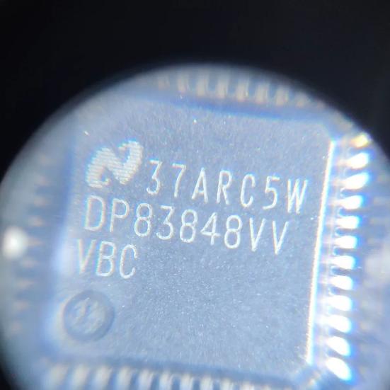
The DP83848CVVX operates as the physical layer (PHY) transceiver in an Ethernet system, implementing the IEEE 802.3 physical layer functions to transmit and receive data over twisted-pair copper cable at 10 Mbps or 100 Mbps.
Physical Coding Sublayer (PCS): For 100BASE-TX, the PCS implements 4B/5B encoding (4 data bits encoded into 5-bit symbols) and scrambles the data to reduce EMI. The encoded data is serialized and transmitted as MLT-3 (Multi-Level Transmit) signals on the twisted pair, where each symbol represents one of three voltage levels. For 10BASE-T, the PCS implements Manchester encoding, where each bit is represented by a voltage transition (low-to-high for 1, high-to-low for 0).
Physical Medium Attachment (PMA): The PMA sublayer performs the analog front-end functions. On the transmit side, the digital data is converted to analog signals by the DAC and driven onto the twisted pair through the line driver. On the receive side, the analog signal from the cable is digitized by the ADC and processed by the adaptive equalizer to compensate for cable attenuation and distortion. The baseline wander compensator corrects for DC offset drift caused by AC coupling in the signal path.
Auto-Negotiation: The DP83848 implements IEEE 802.3u auto-negotiation, which automatically determines the highest common speed and duplex capability with the link partner. During auto-negotiation, the PHY exchanges Fast Link Pulse (FLP) bursts that advertise its capabilities (10/100 Mbps, half/full duplex, Auto-MDIX). The highest common denominator is selected: 100 Mbps full-duplex is preferred, followed by 100 Mbps half-duplex, 10 Mbps full-duplex, and 10 Mbps half-duplex. If the link partner does not support auto-negotiation, the parallel detection circuit detects the presence of 10BASE-T normal link pulses or 100BASE-TX idle signals and defaults to the appropriate speed in half-duplex mode.
Auto-MDIX: The Auto-MDIX feature automatically detects whether the connected cable is straight-through or crossover and internally swaps the transmit and receive pairs to ensure correct connectivity. This eliminates the need to stock both cable types and prevents connection failures due to wrong cable type. Auto-MDIX operates during auto-negotiation and also in forced-speed modes.
MII Interface: In MII mode, the DP83848 transfers data to and from the MAC using a nibble-wide (4-bit) data bus at 25 MHz for 100 Mbps or 2.5 MHz for 10 Mbps. The TX_CLK and RX_CLK signals provide timing reference. TX_EN indicates valid transmit data, RX_DV indicates valid receive data, CRS indicates carrier sense (activity on the medium), and COL indicates collision detection (half-duplex only).
RMII Interface: In RMII mode, the DP83848 uses a 2-bit data bus referenced to a 50 MHz clock, reducing the pin count from 16 (MII) to 8 (RMII). The 50 MHz reference clock is typically provided by the DP83848 CLK_OUT pin, or from an external oscillator. RMII is preferred for new designs due to the lower pin count and simplified PCB routing.
Serial Management Interface: The MDC/MDIO interface provides access to the DP83848 internal register set using the IEEE 802.3 Clause 22 protocol. The MAC controller can read and write PHY registers to configure operating modes, check link status, read PHY identification, enable energy detection, and access cable diagnostic features. The MDC clock frequency can be up to 25 MHz.
Energy Detection: When energy detection mode is enabled (via register bit), the DP83848 monitors the receive line for valid link pulses or data signals. If no activity is detected, the PHY enters a low-power state where most internal circuits are powered down. Periodically, the PHY wakes up briefly to check for link pulses. When a link partner is connected, the PHY detects the link pulses, wakes up fully, and initiates auto-negotiation.
BIST and Diagnostics: The built-in self test (BIST) feature allows the PHY to generate and check pseudo-random data packets internally, verifying the transmit and receive data paths without external equipment. The cable diagnostic test uses time-domain reflectometry (TDR) to estimate cable length and detect cable faults (open, short, impedance mismatch).





 English
  简体中文
简体中文  Español
  العربية