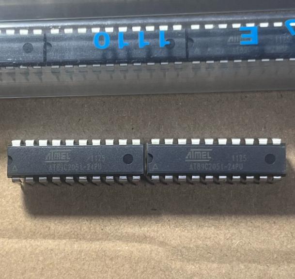
The AT89C2051-24PU is based on the classic 8051 (MCS-51) microcontroller architecture with some modifications for the reduced pin count package.
8051 Core Architecture: The CPU implements the standard MCS-51 instruction set with 111 instructions, including arithmetic (ADD, SUB, MUL, DIV), logical (AND, OR, XOR), data transfer, and Boolean bit manipulation operations. The instruction cycle requires 12 oscillator periods (machine cycle = 12/fOSC), meaning at 24MHz, one machine cycle takes 500ns. Most instructions execute in 1 or 2 machine cycles (12 or 24 oscillator periods). The CPU contains a 128-byte RAM address space (using direct and indirect addressing), an ALU, two 16-bit timer/counters, and a serial port.
Memory Map: The 2KB Flash program memory occupies addresses 0000H to 07FFH. The device has no external memory bus, so the MOVC instructions can only access the internal Flash. The 128-byte RAM is used for general-purpose data storage, the register banks (4 banks x 8 registers = 32 bytes at 00H-1FH), bit-addressable area (16 bytes at 20H-2FH providing 128 directly addressable bits), and the stack (which grows upward from the end of used RAM). The stack pointer defaults to 07H after reset.
Timer/Counters: Timer 0 and Timer 1 are 16-bit up-counters each configurable in one of four operating modes: Mode 0 (13-bit counter), Mode 1 (16-bit counter), Mode 2 (8-bit auto-reload), and Mode 3 (Timer 0 split into two 8-bit counters; Timer 1 stopped). The timers can be clocked from the internal oscillator (divided by 12, giving 2MHz count rate at 24MHz crystal) or from external inputs on T0 (P3.4) and T1 (P3.5). The auto-reload mode (Mode 2) is commonly used for generating precise baud rates for the UART.
Serial Port (UART): The full-duplex UART supports four operating modes: Mode 0 (shift register, synchronous, 8-bit, fixed baud rate = fOSC/12), Mode 1 (asynchronous, 10-bit: start + 8 data + stop, variable baud rate from Timer 1 or Timer 2 overflow), Mode 2 (asynchronous, 11-bit: start + 8 data + TB8 + stop, fixed baud rate = fOSC/32 or fOSC/64), and Mode 3 (asynchronous, 11-bit, variable baud rate). Modes 2 and 3 support 9-bit communication for multiprocessor communication or parity checking.
Analog Comparator: The on-chip comparator compares the voltage on AIN0 (P1.0) against AIN1 (P1.1). The comparator output is internally connected to P3.6, which is not accessible as a general-purpose I/O pin. The comparator can generate an interrupt when the output changes state, enabling the MCU to respond to analog threshold crossings without continuous polling. The comparator has a typical response time of 500ns.
Interrupt System: The AT89C2051 supports 6 interrupt sources with 2 priority levels. Each source has an enable bit in the IE (Interrupt Enable) register and can be individually enabled or disabled. The interrupt vectors are: External Interrupt 0 (0003H), Timer 0 (000BH), External Interrupt 1 (0013H), Timer 1 (001BH), Serial Port (0023H), and Comparator (0043H). When an interrupt is serviced, the CPU pushes the PC onto the stack and jumps to the corresponding vector address.
I/O Port Operation: Port 1 is an 8-bit bidirectional I/O port with internal pull-ups on P1.2-P1.7. P1.0 and P1.1 serve dual functions as comparator inputs and open-drain I/O (no internal pull-ups). Port 3 is a 7-bit bidirectional I/O port (P3.0-P3.5, P3.7) with internal pull-ups. Port 3 pins also serve alternate functions: P3.0/RXD, P3.1/TXD, P3.2/INT0, P3.3/INT1, P3.4/T0, P3.5/T1. The port pins can each sink 20mA, suitable for direct LED drive.
Power-Saving Modes: In Idle mode, the CPU clock is stopped but the peripheral clocks continue running. The UART, timers, and interrupts remain active, and any enabled interrupt or hardware reset will exit Idle mode. In Power-down mode, the on-chip oscillator is stopped, reducing the supply current to approximately 1uA. Only a hardware reset can exit Power-down mode, which requires the RST pin to be held high for at least two machine cycles after the oscillator has restarted (the oscillator restart time depends on the crystal and associated capacitors).





 English
  简体中文
简体中文  Español
  العربية