
Introduction / Industry Overview
Industrial control systems are the central nervous system of modern manufacturing, and their PCBs are the neurons. Unlike consumer electronics—where a reboot is an annoyance—industrial control failures halt production lines, compromise worker safety, and incur costs measured in thousands of dollars per minute of downtime. The global industrial control and automation market was valued at approximately USD 200 billion in 2025, projected to reach USD 320 billion by 2030 (MarketsandMarkets, 2025), driven by Industry 4.0 adoption, smart factory initiatives, and the convergence of IT and OT (Operational Technology) networks.
Industrial control PCBs occupy a fundamentally different design universe from consumer electronics. They must operate continuously for 10–20+ years across extreme temperature ranges (−40°C to +85°C, sometimes −50°C to +105°C), in environments saturated with electromagnetic interference from variable-frequency drives (VFDs), servo motors, arc welders, and switching power supplies. They must withstand humidity, dust, oil mist, corrosive vapors, and constant mechanical vibration. And they must do all of this while maintaining deterministic real-time communication with sub-millisecond latency across industrial networks.
This article examines the core technologies, application cases, and future trajectory of industrial control PCB design, with particular emphasis on reliability engineering, industrial communication protocols, and EMC compliance in the IEC 61131 framework.
Core Technology Analysis
Reliability Engineering: IPC Class 3 and the Zero-Defect Philosophy
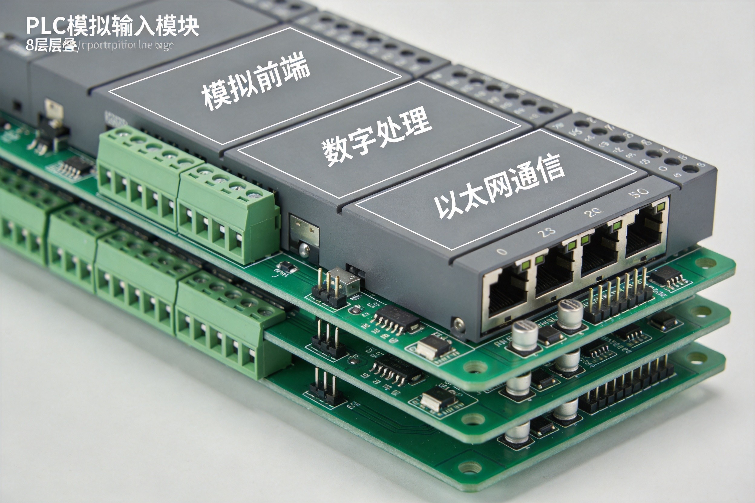
Industrial control PCBs are designed and manufactured to IPC-A-610 Class 3—the highest reliability classification in the IPC quality hierarchy. Class 3 has zero tolerance for many common defects: solder joints must exhibit smooth, uniform appearance with complete wetting; copper traces must maintain strict dimensional tolerances; surface cleanliness must meet ionic contamination limits; and every solder connection must pass both visual inspection and functional testing under stress conditions.
The philosophical difference from consumer electronics (IPC Class 1–2) is stark:
| Dimension | Industrial Control (Class 3) | Consumer Electronics (Class 1–2) |
|---|---|---|
| Design life | 10–20+ years | 2–5 years |
| Operating temperature | −40°C to +85°C (or wider) | 0°C to +50°C (typical) |
| Failure tolerance | Zero for safety-critical functions | Acceptable defect rates defined |
| Solder joint criteria | Complete wetting, smooth fillets | Moderate wetting acceptable |
| Inspection | 100% AOI + ICT + FCT + X-ray | Sampling AOI, limited FCT |
| Design rules | 30–50 active rules | 5–10 active rules |
| Clearance/creepage | Per IEC 61010/61800, often 2–3 mm+ | Minimal, low-voltage optimization |
The practical implications for PCB design are extensive. Trace-to-trace spacing in industrial boards is governed not by routing density optimization but by creepage and clearance requirements from IEC 61010 (measurement and control equipment safety) and IEC 61800 (power drive systems). A 48 V trace may require 1.5–2.0 mm creepage distance from ground, even though the physical voltage could arc across a much smaller gap. High-voltage sections (240 V AC, 480 V AC) may require 3–6 mm clearance, enforced through isolation slots—routed gaps in the PCB that create physical barriers preventing current flow between high-voltage and low-voltage domains.
Material selection reflects the reliability imperative. Standard FR-4 (Tg = 130–140°C) is often inadequate. Industrial designs specify:
- High-Tg FR-4 (Tg ≥170°C) for elevated temperature resistance
- Polyimide substrates for extreme thermal cycling or flexible sections
- Heavy copper (2–4 oz/ft²) for power buses and relay paths, with thermal via arrays for hotspot spreading
- ENIG or ENEPIG surface finishes for humidity resistance and multiple reflow cycle survivability
- Conformal coating (acrylic, silicone, or polyurethane per IPC-CC-830C, 25–250 μm thickness) as secondary protection against moisture, dust, and chemical exposure
Industrial Communication Protocols: The PCB Design Impact
The choice of industrial communication protocol directly shapes PCB architecture, component selection, and layout strategy. Industrial Ethernet now accounts for 76% of new installations (HMS Networks, 2024), with PROFINET leading at ~27% market share, followed by EtherNet/IP at ~23% and EtherCAT at ~9%.
Protocol PCB Design Requirements:
| Protocol | Latency | PCB Impact |
|---|---|---|
| Modbus RTU (RS-485) | ~100 ms polling cycle | Simple: isolated RS-485 transceiver, termination resistors, ESD protection. Lowest PCB complexity. |
| Modbus TCP | ~10–50 ms | Standard Ethernet PHY + magnetics. No real-time hardware needed. W5500 hardwired TCP/IP stack simplifies MCU design. |
| PROFINET RT | 1–10 ms | Standard Ethernet PHY, 802.1Q VLAN priority tagging. Isolated power domain for Ethernet section. 25 MHz crystal (±10 ppm for real-time). |
| PROFINET IRT | 250 μs–1 ms, jitter <1 μs | Dedicated IRT ASIC, high-precision time sync, dual-port switch integrated in IO device. Strictest power supply filtering (ripple ≤30 mV). |
| EtherCAT | 31.25 μs–1 ms | Dedicated ESC (EtherCAT Slave Controller) chip such as ET1200 or LAN9252. Distributed Clock (DC) circuit requires short, clean clock traces. Lowest-jitter power supply mandatory. |
| EtherNet/IP | 1–10 ms | Standard Ethernet PHY with CIP (Common Industrial Protocol) over TCP/UDP. Gigabit variants demand higher SI rigor. |
Common PCB Design Elements Across All Industrial Ethernet Protocols:
-
Galvanic isolation: The Ethernet PHY and network transformer provide 1500 Vrms isolation between the industrial network and the local circuit. The PCB must maintain a clear isolation boundary: primary side (MCU/PHY, digital ground) and secondary side (RJ45/magnetics, isolated ground) must never share a ground plane. The isolation zone requires ≥5 mm creepage distance.
-
Differential pair routing: Ethernet TX+/TX− and RX+/RX− require 100Ω differential impedance with <5 mil length mismatch. Pairs must be tightly coupled, routed away from switching power supplies and motor drive traces, and must never cross ground-plane splits.
-
Isolated power domains: The Ethernet section requires its own isolated DC-DC converter (typically 3.3 V / 1 W), with π-type filtering (ferrite bead + capacitors) at both input and output. Power ripple must be ≤50 mV for standard industrial Ethernet and ≤30 mV for EtherCAT/PROFINET IRT.
-
Surge and ESD protection: RJ45 connectors must include TVS diode arrays (e.g., SRV05-4) for ESD, common-mode chokes for VFD-generated interference, and gas discharge tubes (GDT) + varistors for surge protection per IEC 61000-4-5 (4 kV differential / 6 kV common-mode).
EMC Design for Industrial Environments: IEC 61131-2 Compliance
Industrial environments are electromagnetically hostile. VFDs, servo drives, arc welders, and switching power supplies generate broadband interference that can corrupt sensor signals, crash microcontrollers, and trigger false I/O states. IEC 61131-2 defines the EMC requirements for programmable controllers, covering both emissions (CISPR 11/EN 55011) and immunity (IEC 61000-4 series).
PCB Design Strategies for EMC Compliance:
-
Multi-layer stackups with dedicated ground planes: A 4-layer board (Signal–Ground–Power–Signal) provides the minimum acceptable EMC performance. 6-layer and 8-layer boards are common for complex PLCs, with the stackup arranged so that every signal layer is adjacent to a ground or power plane, minimizing loop area and radiation.
-
Zone-based physical partitioning: The PCB is divided into clearly separated zones: high-voltage/power zone (24 V DC input, relay drivers, motor drivers), digital processing zone (MCU, FPGA, memory), analog sensing zone (ADC, signal conditioning), and communication zone (Ethernet PHY, RS-485 transceivers). Zones are separated by ground-plane splits or isolation slots, with connections only through defined bridge points.
-
Filtering at every interface: Power inputs receive π-type filters (10 μF electrolytic + 100 nF ceramic + common-mode choke). Digital I/O lines use RC filters or Schmitt triggers for noise rejection. Communication ports (CAN, Ethernet) include common-mode chokes and ESD protection. A documented case: an automotive parts factory reduced PLC EMC-related downtime from 12 hours/month to under 0.5 hours/month by implementing comprehensive filtering and shielding per IEC 61131-2.
-
Guard traces and copper pours: Sensitive analog signals (thermocouple inputs, 4–20 mA current loops) are flanked by ground-connected guard traces. Solid ground copper pours with via stitching every 2–3 mm suppress slot-antenna radiation between zones.
-
Conformal coating as EMC enhancer: While primarily for environmental protection, conformal coating also reduces surface leakage currents and prevents conductive contamination (metal dust, coolant mist) from creating parasitic paths between traces—particularly important for creepage compliance in humid environments.
Power Supply Design: The 24 V Industrial Standard
Industrial control equipment universally operates from 24 V DC (IEC 61131-2 allows 20.4–28.8 V, or ±20% tolerance). This wide input range, combined with the noisy industrial supply, demands robust power supply design on the PCB:
-
Front-end protection: Reverse-polarity protection diode, self-resetting fuse (PTC), and varistor at the 24 V input. TVS diodes with breakdown voltage 27–30 V and peak power ≥1000 W suppress surge transients per IEC 61000-4-5.
-
Isolated DC-DC conversion: The main 24 V input is converted to 5 V and 3.3 V through isolated DC-DC modules, providing galvanic separation between field-side and logic-side power domains. This isolation is critical for preventing ground loops between the PLC and field devices.
-
Multi-stage regulation: The 3.3 V rail for the MCU and digital logic is further regulated by low-noise LDOs, while analog reference voltages are derived from dedicated precision references with their own filtered supplies. Power supply rejection ratio (PSRR) at the ADC must exceed 80 dB to maintain measurement accuracy in the presence of switching noise.
Typical Application Cases
Case 1: Multi-Protocol Industrial Ethernet Gateway
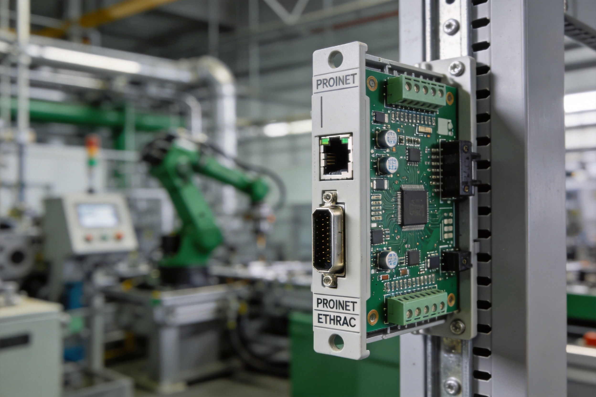
A DIN-rail-mounted gateway provides protocol conversion between PROFINET (as a device/slave) and Modbus RTU (as master or slave), enabling legacy Modbus devices to integrate into PROFINET networks.
PCB Design Approach: 6-layer FR-4 (Tg = 180°C) with the following zone partition: PROFINET Ethernet section (isolated PHY + magnetics + RJ45, with dedicated isolated DC-DC power) on the left third; MCU and protocol processing (ARM Cortex-M7 with external SDRAM) in the center; Modbus RS-485 section (isolated transceiver with 2500 V galvanic isolation) on the right third. The three zones are separated by ground-plane splits with 5 mm clearance zones. The PROFINET section uses a 25 MHz crystal with ±10 ppm stability for IRT timing compliance, with power supply ripple filtered to ≤30 mV through a three-stage LC filter.
Result: PROFINET RT cycle time of 1 ms with zero frame loss, Modbus RTU communication at 115.2 kbps with error rate <10⁻⁶, and IEC 61131-2 EMC compliance (radiated emissions 6 dB below CISPR 11 Class A limits, immunity passing IEC 61000-4-3 at 10 V/m).
Case 2: PLC Analog Input Module with 16-Bit ADC
A 4-channel analog input module for a PLC must measure 4–20 mA current loops and ±10 V voltage signals with 16-bit resolution and 0.1% long-term stability, in an environment with VFD-generated EMI.
PCB Design Approach: 8-layer board with dedicated analog and digital ground planes connected only at the ADC’s ground reference pin. The analog front end uses chopper-stabilized instrumentation amplifiers with 50/60 Hz notch filtering. Guard traces surround all analog input traces, with grounded copper pours on adjacent layers. The ADC’s voltage reference is a precision 2.5 V bandgap device (initial accuracy ±0.02%, temperature drift ≤3 ppm/°C) with its own filtered 5 V supply. All four input channels are galvanically isolated from the PLC backplane through digital isolators (2500 V rating), with isolated power provided by a quad-channel isolated DC-DC converter.
Result: Effective resolution of 15.2 bits (ENOB) at 100 SPS, channel-to-channel crosstalk below −90 dB, and long-term drift within ±0.05% over 12 months at 85°C ambient.
Case 3: Servo Drive Controller with EtherCAT Interface
A 3-axis servo drive controller must achieve 31.25 μs cycle time over EtherCAT, with current loop closure at 20 kHz and position loop closure at 4 kHz, for multi-axis motion synchronization.
PCB Design Approach: 10-layer hybrid stackup with FR-4 in the digital section and low-loss Rogers material for the high-speed EtherCAT differential pairs. The LAN9252 EtherCAT slave controller is placed adjacent to the RJ45 connectors (trace length <20 mm), with its 25 MHz crystal (±10 ppm) positioned within 5 mm. The power section uses 3 oz copper on outer layers for the three H-bridge motor drive stages, with thermal via arrays under each MOSFET. The current sensing resistors (0.001 Ω, 4-terminal Kelvin configuration) are placed directly in the motor phase outputs with differential routing back to the ADC. The MCU (ARM Cortex-M7 with FPGA accelerator) and the EtherCAT controller communicate via a 32-bit parallel bus with matched-length traces (±0.1 mm).
Result: EtherCAT distributed clock synchronization jitter below 100 ns across three axes, current loop bandwidth of 20 kHz, and position synchronization error below 0.01° at 3000 RPM.
Future Development Trends
PROFINET over TSN and Industrial Protocol Convergence
The next evolution of PROFINET replaces proprietary IRT scheduling with IEEE 802.1 Time-Sensitive Networking (TSN) standards (802.1AS for time sync, 802.1Qbv for time-aware scheduling). This is significant because it enables PROFINET determinism to coexist on the same infrastructure with OPC UA Pub/Sub, EtherNet/IP, and other protocols—true IT/OT convergence on a single Ethernet cable. New controllers from Siemens and Phoenix Contact are already shipping with TSN support. For PCB designers, TSN demands even tighter clock distribution networks, more precise impedance control, and multi-protocol PHY integration on a single board. Timeframe: TSN-enabled PROFINET is in early deployment (2026); mainstream adoption expected by 2028–2029.
AI-Driven Predictive Maintenance and Edge Computing
The integration of edge AI on industrial control PCBs—enabling real-time vibration analysis, anomaly detection, and predictive maintenance—requires adding neural network accelerators (NPU), high-speed memory interfaces, and potentially GPU-class computing to boards that must still maintain deterministic real-time control. This creates a unique mixed-signal design challenge: ensuring that AI inference workloads (which are bursty and power-hungry) do not interfere with time-critical control loops through shared power rails or ground impedance. Timeframe: Edge AI modules for industrial gateways are available now; integrated AI+control PCBs will emerge in 2027–2028.
IIoT Integration and Wireless Industrial Networking
The deployment of wireless protocols (Wi-Fi 6/7, Bluetooth LE, LoRaWAN, 5G NR) alongside wired industrial Ethernet on the same PCB is becoming standard for IIoT gateways and smart sensors. This multi-protocol coexistence demands RF design expertise that was previously the domain of telecom equipment—antenna isolation, frequency planning, and coexistence scheduling. The PCB must accommodate both sub-GHz (LoRa) and 2.4/5 GHz (Wi-Fi, BLE) RF sections alongside the deterministic Ethernet interfaces, each with their own shielding and power isolation requirements. Timeframe: Multi-protocol IIoT gateways are in production; 5G-integrated industrial PCBs will enter volume production by 2027–2028.
Conclusion
Industrial control PCB design is defined by a single, non-negotiable imperative: reliability under adverse conditions, sustained over decades. The IPC Class 3 framework, IEC 61131-2 EMC requirements, and the rigorous creepage/clearance rules of IEC 61010 and IEC 61800 establish quantitative thresholds that leave no room for compromise. As industrial networks evolve toward TSN-enabled multi-protocol convergence, edge AI integration, and wireless IIoT connectivity, the PCB designer’s challenge is expanding from “make it survive the factory floor” to “make it survive the factory floor while simultaneously running deterministic real-time control, AI inference, and multi-protocol wireless communication.” For electronics manufacturers serving the industrial sector, the ability to navigate these converging requirements—reliability, real-time performance, and connectivity—is the qualification for market entry.
Need industrial-grade PCB manufacturing with IEC 61131 compliance? Connect with our engineering team to discuss IPC Class 3 production capabilities and industrial Ethernet protocol integration.
 English
  简体中文
简体中文  Español
  العربية