
Bluetooth is a short-range wireless communication technology, whose working principle revolves around the core process of “connection establishment – data transmission”. It achieves stable communication relying on a layered protocol stack and supports multiple working modes to adapt to different scenarios. The following is a detailed illustrated explanation of the Bluetooth working principle:
I. Bluetooth Connection Establishment Process
The connection of Bluetooth devices needs to go through three core steps: “Broadcasting and Scanning – Connection Request – Connection Confirmation”, completing the entire process from initial identification to formal communication establishment:
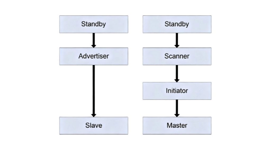
- Broadcasting and Scanning: After a slave device (such as a Bluetooth headset or smart bracelet) enters the broadcasting state, it will regularly send broadcast packets containing key information such as device name, service type, and device ID to actively expose its existence. After a master device (such as a mobile phone or computer) enables the scanning function, it will continuously monitor Bluetooth broadcast signals in the surrounding 2.4GHz frequency band; when the master device captures the broadcast packet of the target slave device, it will send a scan request to it, and the slave device will immediately respond with a scan response after receiving the request. Both parties complete initial identity identification and information interaction, establishing a temporary connection.
- Connection Request: After the initial connection is established, the master device sends a formal connection request to the slave device, which contains connection parameters (such as transmission window offset, connection interval, timeout time, etc.) to agree on the timing rules for subsequent communication. After receiving the request, the slave device will open a receiving window within the specified time window according to the agreed parameters, preparing to receive data packets from the master device to avoid communication timing confusion.
- Connection Confirmation: After the slave device is ready, the master device sends the first synchronization packet (used to calibrate the clocks of both parties to ensure communication synchronization). After the slave device successfully receives it, it immediately replies with a confirmation packet. After the master device receives the confirmation packet, it determines that the connection is successfully established, and both parties switch to the data transmission phase synchronously to start formal data interaction.
II. Data Transmission Process
After the connection is established, Bluetooth devices achieve efficient and reliable data transmission through standardized data packet formats and transmission modes:
(I) Data Packet Format
Bluetooth data packets adopt a fixed structure, which is divided into 5 core fields from top to bottom. Each field has a clear division of labor to ensure the integrity and accuracy of data transmission:
- Preamble: Used to achieve clock synchronization between master and slave devices, ensuring that the timing of data reception and transmission by both parties is consistent and avoiding data misalignment.
- Access Address: Used to distinguish different Bluetooth devices, avoid interference when multiple devices communicate in the same frequency band, and ensure that data is accurately delivered to the target device.
- Header: Contains information such as data length, data type (control data/voice data/file data), and priority, used to inform the receiver how to parse the subsequent data.
- Data Payload: The core data that actually needs to be transmitted, such as voice signals, file content, control commands, etc., which is the core part of the data packet.
- Check Code: Used to detect whether there is loss, error code and other problems during data transmission. The receiver verifies the data integrity through the check code, and requests retransmission if the verification fails.
(II) Transmission Modes
According to application scenarios, Bluetooth supports two core transmission modes to adapt to different types of data transmission needs:
- ACL (Asynchronous Connection-Less) Mode: Mainly used for non-real-time data transmission, such as file transmission, picture sending, device control commands, etc. Data is sent in segments in the form of data packets, supporting a retransmission mechanism. If the receiver does not receive the data or the verification fails, it will feed back to the sender and request retransmission to ensure reliable data transmission, allowing a certain transmission delay.
- SCO (Synchronous Connection-Oriented) Mode: Mainly used for real-time voice communication, such as Bluetooth headset calls, car Bluetooth voice, etc. This mode does not support the retransmission mechanism, giving priority to ensuring transmission real-time. Through fixed timing scheduling, it ensures that the voice signal is continuous and smooth, reduces delay, and meets the quality requirements of voice communication.
III. Bluetooth Protocol Stack Layers (Core Architecture)
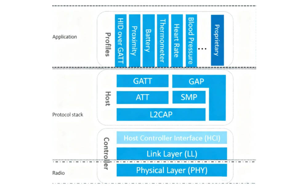
The stable communication of Bluetooth relies on a layered protocol stack. Each layer works independently and cooperates with each other. It is divided into 7 core layers from top to bottom, forming a complete communication link from the underlying wireless signal transmission to the upper-layer application interaction:
- Physical Layer (PHY): The bottom layer of the protocol stack, responsible for the transmission and reception of wireless signals, defining core parameters such as Bluetooth’s operating frequency (2.4GHz ISM band, globally universal and unlicensed), modulation method, and transmission power. It adopts Frequency Hopping Spread Spectrum (FHSS) technology, which avoids interference from devices such as WiFi and ZigBee in the same frequency band by quickly switching communication channels, improving communication stability.
- Link Layer (LL): Directly connected to the physical layer, it is mainly responsible for the management of links between devices, including operations such as connection establishment, maintenance, and disconnection; it is also responsible for the encapsulation, verification, retransmission of data frames, and the scheduling of communication timing, which is the core layer to ensure the reliability of data transmission.
- Host Controller Interface (HCI): As a bridge between the host (such as mobile phone main control) and the controller (Bluetooth chip), it defines the transmission format of commands, events, and data, realizing the host’s control of the Bluetooth controller (such as enabling scanning, initiating connection) and data exchange. This layer can be omitted in some single-chip solutions.
- Logical Link Control and Adaptation Protocol (L2CAP): Connected to the link layer, it provides connection-oriented and connection-less data transmission services for upper-layer protocols; it supports protocol multiplexing (multiple upper-layer protocols share one link), data fragmentation and reassembly (splitting large-size data into small data packets for transmission and reassembling after reception), improving transmission efficiency and link utilization.
- Security Manager Protocol (SMP): Responsible for the security of Bluetooth connections, including device authentication (confirming the legality of connected devices), data encryption (using AES encryption algorithm to prevent data theft), and security key management (generating and updating communication keys), avoiding the leakage or tampering of communication data.
- Attribute Protocol (ATT): Defines the data attributes and operation commands between devices, such as reading data, writing data, notifying data changes, etc., which is the basic protocol for Bluetooth data transmission; it introduces the concept of “attribute”, abstracting device data into operable units to simplify data interaction logic.
- Generic Attribute Profile (GATT): The top layer of the protocol stack, which standardizes the organization and management of attribute data, defines the hierarchical structure of services, characteristics, and attributes (such as defining “battery power” and “heart rate data” as different services and characteristics), realizing interconnection and intercommunication between Bluetooth devices of different brands and types, and is the core of Bluetooth device compatibility.
IV. Supplementary Explanation of BLE Protocol Stack (Bluetooth Low Energy)
Bluetooth Low Energy (BLE for short) is a lightweight version of Bluetooth technology, focusing on low power consumption, short distance, and low data rate, widely used in IoT devices. Its protocol stack structure and configuration have clear specifications, and the core points are as follows:
(I) Protocol Stack Structure and Configuration
- The BLE protocol stack consists of two parts: Controller (including PHY layer and LL layer) and Host (including L2CAP, SMP, ATT, GAP, and GATT layers).
- All Profiles (application profiles) and applications are developed based on GAP (Generic Access Profile) and GATT (Generic Attribute Profile) to ensure device compatibility.
- Single-chip solution: Controller, Host, Profiles, and application layer are all integrated into the same Bluetooth chip, with small size and low power consumption, suitable for small IoT devices (such as smart bracelets and sensors).
- Network Controller mode: Host and Controller are integrated in the same device, while the application layer and Profiles run on another device (such as a PC or microcontroller), realizing communication and control between the two through UART and USB interfaces.
- Dual-chip mode: The Controller runs on an independent Bluetooth controller chip, while the application layer, Profiles, and Host run on another controller (such as a single-chip microcomputer), with clear division of labor, suitable for complex application scenarios.
(II) Core Functions of BLE Protocol Stack
The core function of the BLE protocol stack is to encapsulate application data layer by layer to generate air data packets conforming to the BLE protocol (that is, adding various headers and tails to application data to adapt to wireless transmission requirements). The core functions of each layer are supplemented as follows:
- PHY layer: Directly determines the power consumption, radio frequency sensitivity, and anti-interference ability of the BLE chip, specifies the wireless frequency band and modulation/demodulation method, and is the core guarantee of low power consumption characteristics.
- LL layer: The core and difficulty of the BLE protocol stack, responsible for channel selection, data packet identification, transmission timing control, data integrity verification, ACK reception and retransmission, link management, etc. Some high-end chips (such as Nordic series) can support up to 20 link connections at the same time.
- HCI layer: An optional layer, only used in dual-chip solutions, standardizing the communication protocol and commands between Host and Controller to realize their cooperative work.
- GAP layer: Simply parses the effective data packets of the LL layer, mainly used for device broadcasting, scanning, and initiating connections, with relatively simple functions, and is the basis for device discovery and connection.
- L2CAP layer: Encapsulates the LL layer, distinguishes between encrypted channels and ordinary channels, manages connection intervals, and optimizes link utilization.
- SMP layer: Responsible for the encryption and security management of BLE connections, ensuring communication security while taking into account user experience (such as fast pairing and seamless encryption).
- ATT layer: The layer most frequently contacted by developers, defining user operation commands (such as reading and writing data) and data attributes, abstracting device data into operable “attribute units”.
- GATT layer: Standardizes the content and grouping management of attribute data, and is the key to the interconnection and intercommunication of BLE devices; relying on GATT and various application Profiles, BLE has got rid of the compatibility dilemma and become one of the 2.4G wireless communication technologies with the largest shipment volume currently.
(III) Supplementary Explanation of BLE Device Connection Status Process
To implement a BLE application, three core conditions need to be met: first, a chip supporting BLE radio frequency, second, a supporting BLE protocol stack, and third, an application program developed based on the protocol stack. Among them, the BLE protocol stack is the core bridge connecting the chip and the application, responsible for key operations such as data encapsulation and link management, and is the core of BLE application implementation.
V. Bluetooth Working Modes (Adapting to Different Application Scenarios)
Bluetooth supports three core working modes, which can be flexibly switched according to the number of devices and communication needs, covering various short-range communication scenarios:
- Master-Slave Mode: The most commonly used mode, where the master device initiates the connection and controls the communication timing, and the slave device passively responds to the master device’s instructions. One master device can connect to multiple slave devices at the same time (usually up to 7), realizing point-to-multipoint communication, which is suitable for scenarios such as mobile phones connecting to headsets, keyboards, and mice.
- Broadcasting Mode: The slave device actively broadcasts data to the surrounding area without establishing a connection with any master device, and the broadcast data can be received by multiple master devices at the same time. It is suitable for scenarios such as device discovery, location services, and real-time push of sensor data (such as Bluetooth beacons and environmental sensors).
- Mesh Mode: Multiple Bluetooth devices form a mesh network, and data can be transmitted through jumps between multiple nodes without distinguishing between master and slave devices, supporting large-scale device collaborative communication. It is suitable for scenarios that require multi-device collaboration such as smart homes (such as multi-room lighting control) and industrial automation (such as workshop equipment linkage).
VI. Supplementary Explanation of Bluetooth Low Energy (BLE) Module Working Principle
Bluetooth Low Energy (BLE) minimizes device power consumption through various intelligent optimization methods. Its core architecture is composed of two types of chips, adapting to different application needs:
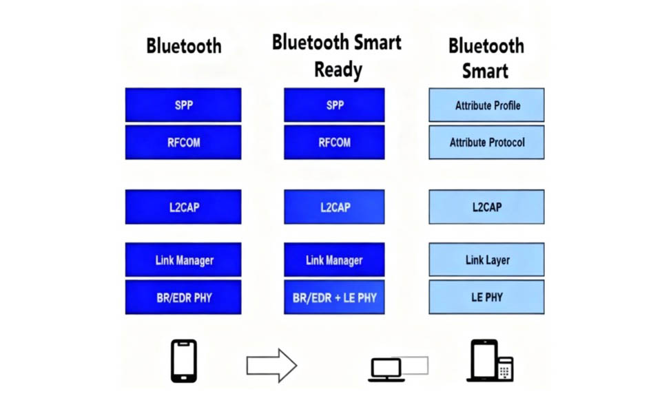
- Single-mode Chip: Optimized specifically for Ultra-Low Power (ULP) operation, only supporting BLE technology, with small size and extremely low power consumption, suitable for small IoT devices (such as smart bracelets and Bluetooth sensors). Single-mode chips can communicate with other single-mode chips and dual-mode chips (dual-mode chips need to switch to BLE mode).
- Dual-mode Chip: Supporting both BLE technology and standard Bluetooth technology (Classic Bluetooth), it can communicate with single-mode chips, standard Bluetooth devices, and other dual-mode chips, adapting to scenarios that need to balance low power consumption and high-speed data transmission (such as mobile phones and tablets).
Summary: Bluetooth technology achieves reliable data transmission through a layered protocol stack and adapts to different scenarios relying on multiple working modes. BLE technology achieves low power consumption characteristics through chip optimization and protocol simplification. Both together promote the wide application of Bluetooth in fields such as headsets, keyboards, smart homes, and the Internet of Things.
 English
  简体中文
简体中文  Español
  العربية