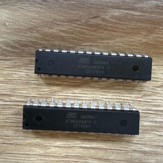
The ATMEGA88PA-PU operates as an 8-bit Harvard-architecture RISC microcontroller with separate program and data memory spaces.
AVR RISC Core: The AVR core uses a 2-stage pipeline (fetch and execute) and a reduced instruction set where most instructions execute in a single clock cycle. The core features 32 x 8-bit general-purpose working registers (R0-R31) that are directly connected to the ALU. Six of these registers (R26-R31) can also serve as three 16-bit indirect address register pointers (X, Y, Z) for data space addressing. The single-cycle instruction execution means that the effective throughput approaches 1 MIPS per MHz, so at 20 MHz the device delivers approximately 20 MIPS.
Harvard Architecture: The program memory (8KB Flash) and data memory (1KB SRAM + 512B EEPROM + I/O registers) are in separate address spaces. The Flash is organized as 4K x 16-bit words (since AVR instructions are 16 bits wide). The data memory space is a linear address space that includes 32 general-purpose registers, 64 I/O registers, 160 extended I/O registers, and 1KB of SRAM. The EEPROM is accessed through special I/O registers (EEAR, EEDR, EECR) and has its own address space (0-511).
picoPower Technology: The picoPower feature set reduces power consumption through several mechanisms: (1) a precision internal oscillator that can run at 32 kHz with only 0.75 uA current; (2) clock gating that shuts down clocks to unused peripherals; (3) an event system that allows peripherals to interact without CPU intervention; (4) sleep modes with progressively lower power consumption. The Power-down mode stops all clocks and oscillators, achieving 0.1 uA. The Power-save mode keeps the 32 kHz oscillator running for the RTC while stopping all other clocks, achieving 0.75 uA. The ADC Noise Reduction mode stops the CPU but keeps the ADC and its clock running for low-noise conversions.
I/O Port Architecture: Each I/O port (PORTB, PORTC, PORTD) has three associated registers: DDRx (Data Direction), PORTx (Data), and PINx (Port Input). When a pin is configured as output (DDRx bit = 1), the PORTx register drives the pin high or low. When configured as input (DDRx bit = 0), the PORTx bit controls the internal pull-up resistor (1 = pull-up enabled). The PINx register reads the actual pin level regardless of direction. Most I/O pins have alternate functions (USART, SPI, I2C, ADC, timers, interrupts) that can be selected by enabling the corresponding peripheral.
Timer/Counter Architecture: The three timer/counters provide timing and PWM capabilities. Timer0 and Timer2 are 8-bit with prescaler, compare match, and waveform generation modes. Timer1 is 16-bit with additional input capture and PWM modes. All timers support PWM output generation using compare match and waveform generation modes. Timer1 supports 16-bit PWM with input capture for frequency and period measurement. Timer2 can use an external 32 kHz crystal as its clock source for real-time counting applications.
ADC Architecture: The 10-bit successive approximation ADC converts analog inputs in 13-260 us depending on the prescaler setting. The ADC features a multiplexer that selects one of 6 (PDIP) or 8 (TQFP/QFN) input channels. A temperature sensor is also available as an ADC input channel. The ADC can operate in single-conversion or free-running mode, and can be triggered by an external signal or a timer compare match. In ADC Noise Reduction sleep mode, the CPU is halted during conversion to minimize digital noise.
In-System Programming (ISP): The Flash and EEPROM can be programmed via the SPI interface while the device is mounted in the target system. During ISP programming, the RESET pin must be held low, and serial data is clocked into the device via MOSI while SCK provides the clock. The ISP protocol allows read, write, erase, and verify operations on both Flash and EEPROM. A fuse system controls device configuration including clock source, startup time, brown-out detection level, and memory partitioning.





 English
  简体中文
简体中文  Español
  العربية