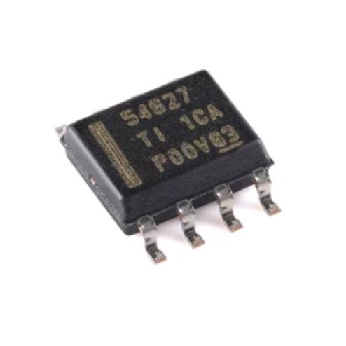
The TPS54627DDAR operates as a fully integrated synchronous buck converter using D-CAP2 mode control with integrated power MOSFETs.
D-CAP2 Mode Control: The control loop uses the D-CAP2 architecture where the output voltage (sensed at the VFB pin through a resistor divider) is compared to an internal 0.760-V reference. The adaptive on-time controller generates PWM pulses whose duration is proportional to VOUT/VIN, maintaining a relatively constant 650 kHz switching frequency. The internal ripple injection circuit adds a synthetic ripple to the VFB signal, ensuring stable operation even with very-low-ESR ceramic output capacitors. No external Type-II or Type-III compensation network is required.
Integrated Power MOSFETs: The high-side NMOS (36 mOhm RDSON) and low-side NMOS (28 mOhm RDSON) are integrated on the same die as the controller. The SW pin is the switch node connecting the two MOSFETs. The bootstrap supply for the high-side driver is provided through an internal diode from VREG5 to VBST, with a 0.1-uF external capacitor between VBST and SW. The adaptive dead-time control prevents shoot-through current by ensuring both MOSFETs are never on simultaneously.
5-V Internal Regulator: The VREG5 pin provides a 5.5-V output from an internal linear regulator that drops VIN. This supplies the gate drive circuitry for both MOSFETs. A 1-uF bypass capacitor to GND is required. VREG5 is active only when EN is high, reducing quiescent current in shutdown.
Soft Start: An external capacitor on the SS pin controls the soft-start time. The SS pin sources 2.3 uA to charge the external capacitor, and the reference voltage tracks the SS pin voltage during startup. The soft-start time is calculated as tSS = CSS x VREF / ISS = CSS x 0.76 / 2.3 uA. For a 22-nF capacitor, tSS is approximately 7.3 ms. During prebiased startup, the converter does not sink current from the output.
Overcurrent Protection: The cycle-by-cycle overcurrent limit senses the peak inductor current through the low-side MOSFET RDSON during the off-time. If the current exceeds the limit (approximately 8 A typical), the high-side MOSFET is prevented from turning on in the next cycle. This provides fast protection against overloads and short circuits.
Output Discharge: When the converter is disabled (EN low or UVLO), the internal discharge MOSFET connects the output to GND through a 200-Ohm resistor, discharging the output capacitors. This ensures the output voltage drops to zero quickly when the converter is turned off, which is important for proper power sequencing.
Overvoltage Protection: If the output exceeds approximately 112 percent of the target voltage, the high-side MOSFET is turned off and the low-side MOSFET is turned on to discharge the output. This protects downstream circuitry from overvoltage damage.
Thermal Shutdown: The internal thermal shutdown circuit disables the converter when the junction temperature exceeds approximately 160 degrees C. The converter automatically restarts when the junction temperature drops by approximately 20 degrees C.





 English
  简体中文
简体中文  Español
  العربية