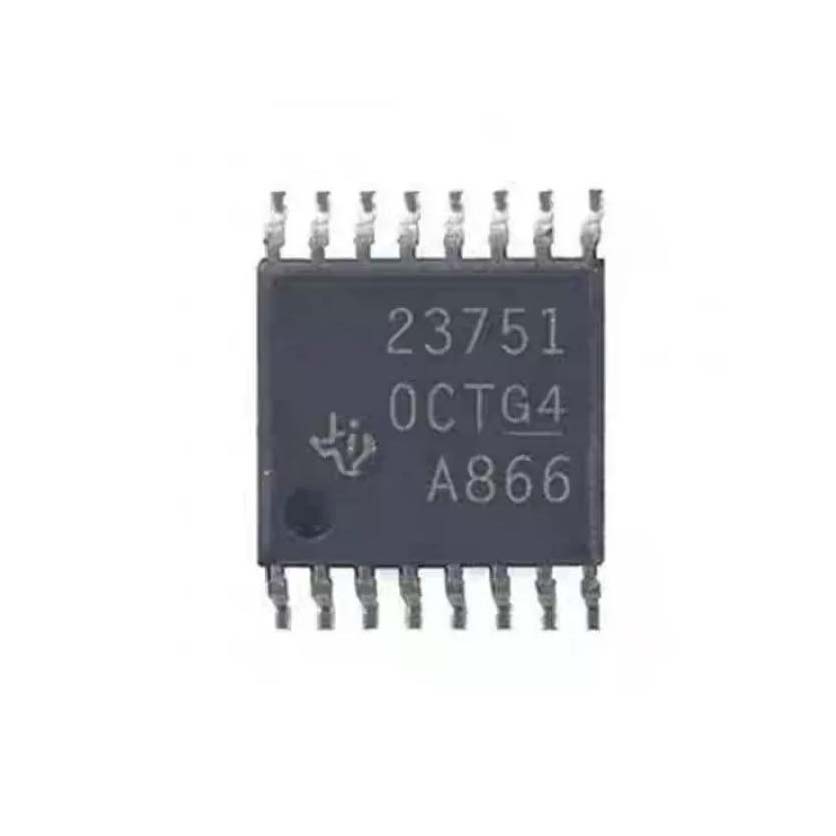
The TPS23751PWPR integrates two major functional blocks: a PoE PD interface and a flyback DC-DC controller, operating together to convert PoE power from an Ethernet cable into a regulated isolated DC output.
PoE PD Interface: When connected to a Power Sourcing Equipment (PSE) through the Ethernet cable, the PD interface first presents a detection signature (24.9 kohm between VDD and VSS) to identify itself as a valid PoE device. After detection, the PSE applies classification voltage, and the CLS pin resistor programs the classification current to signal the PD power class (Class 0-4 for 802.3af, or Class 4 for 802.3at Type 2 at 25.5W). Once classification is complete, the PSE applies full power (44-57V). The internal 0.5-ohm, 100V hotswap MOSFET between RTN and VSS is initially off, with inrush current limited to 140 mA while the bulk capacitor on VDD charges. After the inrush period, the MOSFET turns on fully, allowing operating current up to the current limit threshold (minimum 850 mA). The DEN pin can be pulled to VSS to disable the pass MOSFET, and the APD pin allows an auxiliary power source to take priority over PoE.
DC-DC Controller: The current-mode flyback controller operates from the PoE input voltage (typically 44-57V). The switching frequency is set by a resistor on the RT pin (referenced to ARTN). The controller uses peak current-mode control: the CS pin senses the primary-side MOSFET current through an external sense resistor, and the PWM comparator terminates the GATE on-time when the sensed current reaches the threshold set by the CTL voltage. The VB pin provides a 5V bias supply. The VC pin is the converter bias voltage bypassed with a minimum 0.47 uF capacitor to ARTN. The SRT pin sets the threshold for PWM-to-VFO transition, allowing the controller to enter variable frequency operation at light loads for higher efficiency.
Synchronous Rectification Control: The SRD output disables external synchronous rectifier MOSFETs during VFO mode to prevent reverse current flow. This enables seamless transition between continuous conduction mode (with sync rectification) and VFO mode (with diode rectification for light-load efficiency).
Adapter ORing: The APD input monitors an auxiliary power source. When APD is raised 1.5V above ARTN, the PoE pass MOSFET is disabled and T2P is forced active, enabling seamless switchover from PoE to adapter power without output interruption.





 English
  简体中文
简体中文  Español
  العربية