LM3914N


10-LED dot/bar display driver, linear, adj Vref 1.2-12V, 2-30mA LED current, expandable 100 steps, PDIP-18, 3-15V, 0~70C, NRND

5000

Effective Inventory
Go to Inquiry

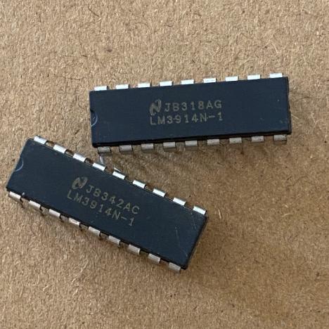
Image for reference only

Manufacturer Part:

LM3914N

Package:

PDIP-18 (NFK) (19.3 x 9.4 mm, 2.54mm pitch)

Brand:
Product Categories:
Other recommendations you may be interested in.
Description

The LM3914N from Texas Instruments is a monolithic dot/bar display driver that senses analog voltage levels and drives 10 LEDs, providing a linear analog display, in an 18-pin PDIP package. Key specifications: 10 LED driver outputs with individually regulated current; bar or dot display mode externally selectable; expandable to displays of 100 steps by chaining multiple LM3914s; internal adjustable voltage reference from 1.2 V to 12 V; operates with single supply of less than 3 V; inputs operate down to ground; output current programmable from 2 mA to 30 mA; no multiplex switching or interaction between outputs; input withstands plus or minus 35 V without damage or false outputs; LED driver outputs are current-regulated open-collectors; outputs can interface with TTL or CMOS logic; internal 10-step voltage divider is floating and can be referenced to a wide range of voltages; indication non-linearity typically 0.5 percent; 0 to 70 degrees C operating temperature; supply voltage 3 V to 15 V; LED supply up to 25 V. The N suffix denotes 18-lead PDIP package. NOTE: This product is no longer in production; new designs should consider alternatives.

The LM3914N from Texas Instruments is a classic monolithic integrated circuit that senses analog voltage levels and drives 10 LEDs to provide a linear analog display. It is one of the most iconic and widely-used display driver ICs in the electronics industry, having been in continuous production since its introduction by National Semiconductor (now part of TI) in the early 1980s.

The LM3914 is fundamentally a 10-step linear voltmeter on a chip. It contains an input buffer, 10 precision comparators, a 10-step resistor divider, an adjustable voltage reference, and 10 current-regulated LED driver outputs. The only external components needed for a basic application are the 10 LEDs, one programming resistor (which sets the LED brightness), and a power supply.

The bar or dot display mode is selected by a single pin (pin 9). In bar mode, all LEDs up to the level corresponding to the input voltage are lit, creating a bar graph. In dot mode, only the single LED corresponding to the input voltage level is lit, creating a moving dot. The dot mode has a small overlap (about 1 mV) between adjacent segments to ensure that at least one LED is always lit, preventing ambiguous display states.

The internal voltage reference generates a nominal 1.25 V between the REF OUT (pin 7) and REF ADJ (pin 8) pins. Using two external resistors (R1 and R2), the reference voltage can be adjusted from 1.2 V to 12 V. The same resistor that sets the reference voltage also programs the LED current: LED current is approximately 10 times the current flowing out of the REF OUT pin. This elegant design means that a single resistor sets both the full-scale voltage and the LED brightness.

The floating 10-step voltage divider is a key feature. Both ends of the divider (RHI at pin 6 and RLO at pin 4) are accessible, allowing the display to span any voltage range, not just 0 to VREF. For example, an expanded-scale meter can display 4.5 V to 5.0 V full-scale by connecting RHI to 5.0 V and RLO to 4.5 V. The 10 LEDs then represent 50 mV steps, providing much finer resolution than a 0-5 V display.

The LM3914 can be cascaded (chained) to create displays with 20, 30, or more segments. In dot mode, pin 9 of the lower-voltage LM3914 is connected to pin 1 of the next higher LM3914, and special internal circuitry ensures that only one LED is lit across all cascaded devices. In bar mode, the outputs of multiple LM3914s operate independently.

The LM3914N is the PDIP-18 package version, popular for prototyping and educational applications. The through-hole package allows easy breadboard use and hand soldering. The LM3914 is also available in PLCC-20 (LM3914FN) for surface-mount applications.

IMPORTANT: TI has designated the LM3914 as not recommended for new designs (NRND), and the product is no longer in production. However, it remains widely available from distributors and second-source manufacturers. For new designs, alternatives include the LM3914 from other manufacturers, discrete LED driver solutions with MCU control, or integrated LED driver ICs with I2C/SPI interfaces.

The LM3914N operates as a linear 10-step analog-to-LED display converter with an internal voltage reference and precision resistor divider.

Input Buffer: The signal input at pin 5 (SIG) enters a high-impedance buffer amplifier that presents very low input bias current (25 nA typical). The buffer accepts input voltages from ground (0 V) up to VCC – 1.5 V, and is protected against overvoltage up to plus or minus 35 V. The buffer output drives the non-inverting inputs of all 10 comparators simultaneously.

Precision Resistor Divider: The internal resistor string consists of 10 equal-value resistors connected in series between the RHI (pin 6) and RLO (pin 4) pins. The total resistance is approximately 10 kOhm (1 kOhm per step). The voltage at each tap of the divider provides the reference voltage for one comparator. Because the resistors are monolithically integrated and laser-trimmed, their matching is very precise (typically 0.5 percent non-linearity), ensuring even spacing between LED thresholds.

Comparator Array: Each of the 10 comparators compares the buffered input voltage (at the non-inverting input) with the voltage at its respective divider tap (at the inverting input). When the input voltage exceeds the tap voltage, the comparator output activates its corresponding LED driver. In bar mode, all comparators with tap voltages below the input are activated, lighting all LEDs up to the current level. In dot mode, only the comparator corresponding to the highest activated tap is allowed to drive its LED, with adjacent comparators inhibited by the mode control logic.

Mode Pin Logic: Pin 9 (MODE) controls the display mode and the dot-mode carry function. When pin 9 is connected to VCC (pin 3), the chip is in bar mode: all comparators below the input level drive their LEDs. When pin 9 is left open, the chip is in dot mode: only one LED is lit. When pin 9 is pulled low by an external signal (such as the output of a higher LM3914 in a cascaded chain), the current LED is forced off to implement the dot-mode carry.

Voltage Reference: The internal bandgap reference generates a nominal 1.25 V between REF OUT (pin 7) and REF ADJ (pin 8). The reference voltage is set by external resistors R1 and R2: VREF = 1.25 x (1 + R2/R1) + IADJ x R2, where IADJ is typically 75 uA. The current flowing through R1 and R2 is also the programming current for the LED drivers: each lit LED draws approximately 10 times the reference current. For example, if the reference load is 1 mA, each LED draws approximately 10 mA.

LED Current Regulation: Each LED driver is a current-regulated open-collector NPN transistor. The current through each lit LED is held constant regardless of the LED supply voltage (VLED) from about 2 V to 17 V. This eliminates the need for individual LED series resistors. The LED current matching between outputs is typically within 0.12 mA at 2 mA and 1.2 mA at 20 mA.

Cascading: Multiple LM3914s can be chained to create displays with more than 10 segments. In dot mode, pin 9 of the lower-voltage device connects to pin 1 of the higher-voltage device. When an LED in the higher device lights, the current through pin 1 pulls pin 9 of the lower device below VLED, which activates comparator C2 internally, turning off LED 10 of the lower device. This ensures only one LED is lit across all cascaded devices.

Pin Name Type Description
1 LED1 Output LED driver output 1 (lowest threshold); open-collector current-regulated output; sinks current through LED 1 when the input voltage exceeds the first divider tap; the LED cathode connects here, anode to VLED through the LED; current is regulated by the reference programming resistor
2 V- Power Negative supply / ground; connects to circuit ground; all LED driver current returns through this pin; important: all signal grounds, reference grounds, and bottom of the resistor divider should connect to this pin at a single point to avoid ground-loop errors
3 V+ Power Positive supply voltage; 3 V to 15 V (max 25 V absolute); bypass with 2.2 uF tantalum or 10 uF electrolytic capacitor to pin 2 if LED supply leads are long; the IC draws only a few mA from this pin, as most LED current comes from the separate VLED supply
4 RLO Reference Resistor divider low end; the bottom of the internal 10-step voltage divider connects here; set this to the lowest voltage to be displayed (typically 0 V for a 0-to-VREF display); for expanded-scale meters, set to the minimum display voltage; bypass with 0.001-0.1 uF capacitor in noisy environments
5 SIG Input Signal input; the analog voltage to be displayed; high input impedance (25 nA bias current); accepts signals from ground to VCC-1.5 V; protected against overvoltage to plus or minus 35 V (with current limit of plus or minus 3 mA); for higher voltage tolerance, add a 39 kOhm series resistor (allows plus or minus 100 V inputs)
6 RHI Reference Resistor divider high end; the top of the internal voltage divider connects here; set this to the voltage that lights LED 10 (full-scale); typically connected to REF OUT (pin 7) for a 0-to-VREF display; for expanded-scale meters, connect to the maximum display voltage
7 REF OUT Reference Reference voltage output; nominal 1.25 V above REF ADJ (pin 8); the current drawn from this pin sets the LED brightness (LED current approximately 10x reference current); connect programming resistors R1 and R2 between REF OUT, REF ADJ, and ground to set both the reference voltage and LED current; VREF = 1.25 x (1 + R2/R1)
8 REF ADJ Reference Reference voltage adjust; the bottom of the internal reference amplifier; connect R1 from pin 7 to pin 8 and R2 from pin 8 to ground; the reference voltage is developed across R1 and R2; the adjust pin current is approximately 75 uA flowing out of the pin
9 MODE Input Mode select; connect to V+ (pin 3) for bar mode; leave open for dot mode; for cascading in dot mode, connect pin 9 of the lower device to pin 1 (LED1 output) of the next higher device; in dot mode, pulling this pin low forces all LEDs off; the pin 9 voltage is sensed by internal comparators C1 and C2 for mode and carry control
10 LED10 Output LED driver output 10 (highest threshold); open-collector current-regulated output; sinks current through LED 10 when the input voltage exceeds the tenth divider tap; in dot mode cascading, this output is disabled when a higher device lights its LED1
11 LED9 Output LED driver output 9; same characteristics as LED1
12 LED8 Output LED driver output 8; same characteristics as LED1
13 LED7 Output LED driver output 7; same characteristics as LED1
14 LED6 Output LED driver output 6; same characteristics as LED1
15 LED5 Output LED driver output 5; same characteristics as LED1
16 LED4 Output LED driver output 4; same characteristics as LED1
17 LED3 Output LED driver output 3; same characteristics as LED1
18 LED2 Output LED driver output 2; same characteristics as LED1
Application Description
Audio VU Meter Display audio signal level on 10-LED bar graph; rectified audio signal drives SIG input; RHI set to peak audio level; bar mode shows signal intensity; LED current set for desired brightness; 20-segment display uses two cascaded LM3914s; classic application for hi-fi and recording equipment
Battery Level Indicator Monitor battery voltage with 10-LED bar or dot display; voltage divider scales battery voltage to SIG input; RHI and RLO set display range (e.g., 10 V to 14 V for 12 V battery); dot mode conserves power; bar mode gives clear visual indication; 3 V minimum operation works with single Li-ion cell
Temperature Display Display temperature reading from thermistor or sensor IC; voltage proportional to temperature drives SIG; expanded-scale display (e.g., 18-28 degrees C) provides finer resolution; bar mode shows temperature range at a glance; useful for HVAC, incubators, and environmental monitoring
Voltage Regulator Tester Test and grade 5 V regulators by displaying output voltage deviation; expanded scale (4.5 V to 5.5 V) with 100 mV per LED; color-coded LEDs (red=bad, green=good, yellow=marginal); bar mode clearly shows voltage stability; classic TI application note circuit
Signal Strength Meter Display RF signal strength from detector output; bar graph shows signal intensity; useful for antenna alignment and RF troubleshooting; 80 kHz bandwidth allows audio-rate signal monitoring; cascaded displays for wider dynamic range
Model Manufacturer Compatibility Key Difference
LM3915N TI Pin-Compatible, Logarithmic Same pinout and package; logarithmic 3 dB/step display (vs linear); designed for audio level metering; 10 steps cover 30 dB range; use for audio VU meters where logarithmic response is needed; same LED current programming
LM3916N TI Pin-Compatible, VU Scale Same pinout and package; VU scale calibrated to ANSI C16.5 standard; specifically designed for professional audio VU meters; combines linear and logarithmic steps; use for broadcast and recording VU meters
HT16K33 Holtek Modern I2C Alternative LED matrix driver with I2C interface; drives 128 LEDs (16×8); supports key scanning; requires MCU for level sensing; more flexible but more complex; use for new designs needing digital control and matrix driving
IS31FL3731 Lumissil Modern I2C Alternative 8×9 LED matrix driver with I2C interface; individual LED PWM dimming (8-bit); animation engine; use for modern LED display designs requiring digital control and animation effects
MCU + ADC + LED Driver Various Custom Alternative Use a small MCU with ADC to measure voltage and drive LEDs via GPIO or I2C LED driver; most flexible approach; can implement any display pattern, color, and animation; higher firmware complexity; recommended for new designs where LM3914 is NRND
Recommend Parts
PMIC for AM335x, 3 bucks, 2 LDOs, battery charger, WLED, I2C, VQFN-48

Brand:

Package:

VQFN-48 (6×6 mm, 0.4 mm pitch)
In stock:
8909pcs

Cargo cycle: 3~7 Days
The minimum order is 1

Go to Inquiry
Octal D-type flip-flop, edge-triggered, async clear, 28MHz, SOP-20

Brand:

Package:

SOP-20 (NS) (12.6×7.8 mm)
In stock:
8359pcs

Cargo cycle: 3~7 Days
The minimum order is 1

Go to Inquiry
3-to-8 decoder/demux, active-low outputs, 3 enable inputs, 15ns, PDIP-16

Brand:

Package:

PDIP-16 (24.33×9.4 mm, Through-Hole)
In stock:
11952pcs

Cargo cycle: 3~7 Days
The minimum order is 1

Go to Inquiry
2W mono Class-AB audio amp, BTL speaker + SE headphone, 2.5-5.5V, HVSSOP-8

Brand:

Package:

HVSSOP-8 (DGN) (3.0×4.9 mm, PowerPAD)
In stock:
3337pcs

Cargo cycle: 3~7 Days
The minimum order is 1

Go to Inquiry
10/100 Ethernet PHY, MII/RMII/SNI, Auto-MDIX, 270mW, LQFP-48, commercial

Brand:

Package:

LQFP-48 (7×7 mm)
In stock:
14754pcs

Cargo cycle: 3~7 Days
The minimum order is 1

Go to Inquiry
Octal bus transceiver, 3-state outputs, 2-6V, 12ns tpd, TSSOP-20

Brand:

Package:

TSSOP-20 (6.5×6.4 mm)
In stock:
2638pcs

Cargo cycle: 3~7 Days
The minimum order is 1

Go to Inquiry
Quality Assurance

All electronic components we source from our partnered supply chains go through strict incoming inspections.Through careful testing, we ensure everything delivered to customers is genuine original parts and meets quality requirements.In addition, we keep complete inspection records to make the entire supply chain process clear and traceable.

Certification
We have obtained a number of professional certifications and built our own professional testing laboratory.This ensures that every product we deliver to our customers meets the highest quality requirements.We conduct tests in strict accordance with procedures to ensure stable product quality and accurate parameters.To guarantee genuine original parts, we also cooperate with reliable third-party testing institutions for strict quality inspection.We always attach great importance to quality and fully comply with industry standards, relevant regulations, and ISO 9001:2015 requirements.

Shipping & Payment

All electronic components we source from our partnered supply chains go through strict incoming inspections.Through careful testing, we ensure everything delivered to customers is genuine original parts and meets quality requirements.In addition, we keep complete inspection records to make the entire supply chain process clear and traceable.

Certification
We have obtained a number of professional certifications and built our own professional testing laboratory.This ensures that every product we deliver to our customers meets the highest quality requirements.We conduct tests in strict accordance with procedures to ensure stable product quality and accurate parameters.To guarantee genuine original parts, we also cooperate with reliable third-party testing institutions for strict quality inspection.We always attach great importance to quality and fully comply with industry standards, relevant regulations, and ISO 9001:2015 requirements.

Service & Packaging

All electronic components we source from our partnered supply chains go through strict incoming inspections.Through careful testing, we ensure everything delivered to customers is genuine original parts and meets quality requirements.In addition, we keep complete inspection records to make the entire supply chain process clear and traceable.

Certification
We have obtained a number of professional certifications and built our own professional testing laboratory.This ensures that every product we deliver to our customers meets the highest quality requirements.We conduct tests in strict accordance with procedures to ensure stable product quality and accurate parameters.To guarantee genuine original parts, we also cooperate with reliable third-party testing institutions for strict quality inspection.We always attach great importance to quality and fully comply with industry standards, relevant regulations, and ISO 9001:2015 requirements.



