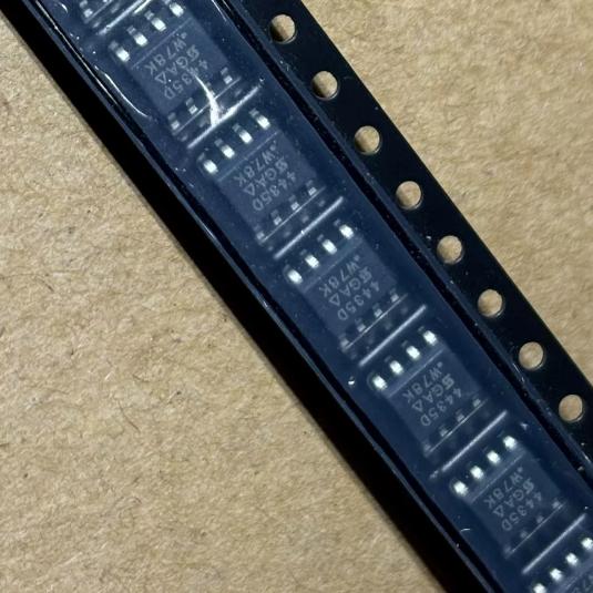
The SI4435DDY-T1-GE3 from Vishay Siliconix is a P-channel enhancement-mode TrenchFET power MOSFET rated for -30V drain-source voltage and -8.1A continuous drain current in an SOIC-8 (SO-8) surface-mount package. It is one of the most popular P-channel MOSFETs for load switching and battery management applications, offering an excellent balance of low on-resistance, moderate gate charge, and wide availability.
The TrenchFET technology uses a vertical trench gate structure that significantly reduces the channel resistance compared to planar MOSFET architectures. By etching deep trenches into the silicon and lining them with the gate oxide and gate electrode, the channel is formed on the vertical sidewalls of the trench. This increases the channel width per unit area, reducing the specific on-resistance (RDS(on) x area) and enabling lower RDS(on) in a smaller die. The SI4435DDY achieves 24mOhm maximum RDS(on) at VGS=-10V in a standard SO-8 package, making it suitable for load switching applications where voltage drop and power dissipation must be minimized.
The SO-8 (150mil) package is the industry-standard footprint for medium-power surface-mount MOSFETs. It features a gull-wing lead configuration with three source pins (1-3), one gate pin (4), and four drain pins (5-8) connected to the die attach pad for thermal dissipation. The multiple source and drain pins reduce package parasitic inductance and provide parallel current paths, improving current handling and thermal performance. The LITTLE FOOT designation indicates that this package has been modified to provide the heat transfer capabilities required by power devices.
As a P-channel MOSFET, the SI4435DDY is turned on by applying a negative gate-source voltage (VGS < 0). For a high-side load switch application with a 5V supply, the gate is pulled to GND (VGS = -5V) to turn on the MOSFET, connecting the source (connected to 5V supply) to the drain (connected to the load). When the gate is pulled to the source voltage (VGS = 0V), the MOSFET turns off, disconnecting the load. This simple high-side switching configuration is the primary use case for P-channel MOSFETs, as it avoids the need for a gate drive voltage above the supply rail that N-channel high-side switches require.
The RDS(on) specification varies significantly with gate drive voltage. At VGS=-10V, the maximum RDS(on) is 24mOhm, while at VGS=-4.5V, it increases to 35mOhm. For a 5V system where the gate can be driven to GND (VGS=-5V), the RDS(on) falls between these values, typically around 28-30mOhm. This voltage-dependent RDS(on) must be considered in thermal calculations, as higher RDS(on) leads to more power dissipation at the same load current.
The gate charge of 15nC at VGS=-4.5V and 32nC at VGS=-10V determines the switching energy and the gate drive current required for a given switching frequency. For load switching applications where the MOSFET switches infrequently (e.g., power-on/off), the gate charge has minimal impact on power dissipation. For PWM applications at higher frequencies, the gate charge must be considered in the total power budget.
The body diode (inherent in all MOSFETs) has a forward voltage of 0.75V typical at 2A and a reverse recovery time of 34ns. This body diode can conduct current when VDS is negative (drain below source), which is the normal forward direction for a P-channel MOSFET. In load switching applications, the body diode may briefly conduct during transients before the MOSFET channel fully enhances.
The -T1-GE3 suffix provides important ordering information: T1 indicates tape-and-reel packaging (2,500 units per reel), and GE3 indicates both lead-free (per RoHS) and halogen-free (per IEC 61249-2-21). The -E3 suffix (SI4435DDY-T1-E3) is lead-free but not halogen-free. The GE3 variant is preferred for environmentally sensitive applications and regions with strict halogen-free requirements.






 English
  简体中文
简体中文  Español
  العربية




