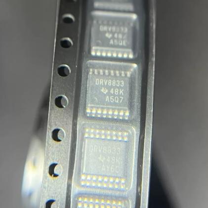
DRV8833PWPR


Dual H-bridge motor driver, 2.7-10.8V, 1.5A RMS/2A peak, 360mOhm, PWM current regulation, parallel mode 3A, HTSSOP-16, Active

2100

Effective Inventory
Go to Inquiry

Image for reference only

Manufacturer Part:

DRV8833PWPR

Package:

HTSSOP-16 (PWP) with PowerPAD (5.00 x 6.40 x 1.05 mm)

Brand:
Product Categories:
Other recommendations you may be interested in.
Description

The DRV8833PWPR from Texas Instruments is a dual H-bridge current-controlled motor driver in a 16-pin HTSSOP (PWP) package with PowerPAD (5.00 x 6.40 mm). It can drive two DC brush motors or one bipolar stepper motor. Motor supply voltage: 2.7V to 10.8V. Low MOSFET on-resistance: HS+LS = 360mOhm typical at 5V/25C. Output current per H-bridge: 1.5A RMS / 2A peak (PWP package). Outputs can be paralleled for 3A RMS / 4A peak operation. PWM winding current regulation and current limiting via external sense resistors on AISEN/BISEN pins. Simple PWM interface: 4 logic inputs (AIN1, AIN2, BIN1, BIN2) control motor direction and brake. nSLEEP pin for low-power sleep mode (1.6uA typical at 5V). nFAULT open-drain output for overcurrent, short-circuit, UVLO, and thermal shutdown fault reporting. Internal charge pump for high-side gate drive (0.01uF cap between VCP and VM). VINT internal 3.3V regulator bypass (2.2uF cap to GND). Both fast and slow decay modes supported. Operating temperature: -40C to +85C. Active product, RoHS compliant, EAR99.

The DRV8833PWPR from Texas Instruments is a versatile dual H-bridge motor driver that provides an efficient and compact solution for driving two DC brush motors or one bipolar stepper motor. Housed in a thermally enhanced 16-pin HTSSOP package with PowerPAD, it delivers up to 1.5A RMS per H-bridge with a low MOSFET on-resistance of 360mOhm (HS+LS combined), minimizing power dissipation and maximizing efficiency.

The DRV8833 is one of TI’s most popular motor driver ICs, widely used in battery-powered toys, POS printers, security cameras, office automation equipment, gaming machines, and robotics. Its combination of wide supply range (2.7V to 10.8V), moderate current capability (1.5A RMS per bridge), PWM current regulation, and comprehensive protection features makes it a go-to choice for many low-voltage motor drive applications.

The device features two independent H-bridges, each consisting of N-channel power MOSFETs in a standard H-bridge configuration. Each H-bridge can independently drive a DC motor bidirectionally, or the two H-bridges can work together to drive a single bipolar stepper motor. The outputs can also be paralleled (AOUT1+BOUT1, AOUT2+BOUT2) to deliver 3A RMS and 4A peak to a single motor, which is useful for driving higher-current loads with a single device.

The PWM current regulation feature uses external sense resistors connected between the AISEN/BISEN pins and GND to set the current regulation threshold. The internal 200mV reference comparator monitors the voltage across the sense resistor and chops the current when it exceeds the threshold. This allows precise control of motor winding current, which is essential for stepper motor applications where consistent torque and microstepping accuracy depend on accurate current setting. The current trip point is calculated as: I_trip = 0.2V / R_sense. For a 0.2Ohm sense resistor, I_trip = 1A.

The simple 4-pin PWM control interface (AIN1, AIN2, BIN1, BIN2) requires no serial communication or register programming. Each pair of inputs directly controls the state of the corresponding H-bridge outputs. This makes the DRV8833 easy to interface with any microcontroller using just 4 GPIO pins. Speed control is achieved by applying PWM signals to the input pins.

The HTSSOP-16 (PWP) package with PowerPAD provides the best thermal performance among the available DRV8833 package options. The PowerPAD (exposed thermal pad on the bottom of the package) must be soldered to the PCB ground plane for proper heat dissipation. The junction-to-board thermal resistance is 28.8C/W for the PWP package, compared to 44.7C/W for the WQFN (RTE) package, allowing higher continuous current in the same ambient temperature.

The PWP package also offers the highest current rating of 1.5A RMS per bridge (compared to 0.6A RMS for the WQFN package and 0.5A RMS for the TSSOP PW package). The 2A peak current per bridge can handle motor startup transients and brief overloads. When outputs are paralleled, the combined 3A RMS and 4A peak capability can drive substantial loads.

The DRV8833PWPR is the tape-and-reel version (2000 units per reel), while the DRV8833PWP is the tube version (90 units per tube). Both have identical electrical characteristics.

The DRV8833PWPR operates as a dual H-bridge motor driver with PWM current regulation capability.

H-Bridge Operation: Each H-bridge consists of four N-channel power MOSFETs arranged in a bridge configuration. N-channel MOSFETs are used for both high-side and low-side positions, providing lower on-resistance than P-channel alternatives. The combined HS+LS on-resistance of 360mOhm results in minimal voltage drop and power dissipation at rated current. At 1.5A, the voltage drop across the MOSFETs is approximately 540mV, and the power dissipation per bridge is approximately 810mW.

Charge Pump: Since N-channel MOSFETs are used for the high-side switches, a gate voltage above the source (output) voltage is needed to turn them on. The internal charge pump generates this elevated gate drive voltage. A 0.01uF capacitor connected between VCP and VM stores the charge pump output. The charge pump operates automatically and requires no external timing components. It provides sufficient gate drive across the full 2.7V to 10.8V supply range.

PWM Current Regulation: When current regulation is enabled (sense resistors connected to AISEN/BISEN), the driver monitors the motor current through the sense resistors. When the current exceeds the threshold (I_trip = 0.2V / R_sense), the driver enters a decay mode for a fixed off-time period. The DRV8833 supports both fast decay (outputs high-impedance, current flows through body diodes) and slow decay (outputs shorted, current recirculates through low-side MOSFETs). Fast decay provides faster current reduction but may cause voltage spikes; slow decay provides smoother current waveform but slower reduction. The decay mode is determined by the state of the input pins during the off-time.

Logic Control Truth Table: xIN1=0, xIN2=0: Coast (both outputs high-Z, fast decay). xIN1=1, xIN2=0: Forward (xOUT1=HIGH, xOUT2=LOW). xIN1=0, xIN2=1: Reverse (xOUT1=LOW, xOUT2=HIGH). xIN1=1, xIN2=1: Brake (both outputs LOW, slow decay). PWM speed control is achieved by toggling between the active state (forward or reverse) and the coast or brake state at a frequency above the motor’s mechanical response bandwidth (typically 10kHz to 50kHz).

Paralleling Outputs: For higher-current applications, the two H-bridges can be paralleled by connecting AOUT1 to BOUT1 and AOUT2 to BOUT2, and driving AIN1=BIN1 and AIN2=BIN2 simultaneously. This effectively doubles the current capacity to 3A RMS and 4A peak. The sense resistors should also be paralleled (or a single sense resistor with half the resistance should be used) to maintain the same current trip threshold.

Sleep Mode: The nSLEEP pin provides a low-power sleep mode. When driven LOW, all internal circuitry including the charge pump is disabled, and the outputs enter a high-impedance state. The supply current drops to 1.6uA typical (5V), preserving battery life in always-on applications. An internal pulldown resistor (500kOhm) ensures the device enters sleep mode if the nSLEEP pin is left floating. Wake-up time from sleep is approximately 155us, which includes charge pump startup and regulator stabilization.

Protection Circuits: Overcurrent protection (OCP) limits current through each MOSFET to a safe level (approximately 3-4A) by disabling the affected bridge. Thermal shutdown (TSD) disables both bridges when the junction temperature exceeds approximately 150C. Undervoltage lockout (UVLO) disables the outputs when VM drops below approximately 2.5V. Short-circuit protection detects output-to-supply and output-to-ground faults. All fault conditions are reported through the nFAULT open-drain output, which requires an external pull-up resistor.

Pin (PWP) Name Type Description
1 nSLEEP Input Sleep mode input; logic HIGH = normal operation; logic LOW = low-power sleep mode (1.6uA typical); internal pulldown (500kOhm) ensures sleep if pin floats; wake-up time ~155us; toggling nSLEEP resets all internal logic
2 AOUT1 Output Bridge A output 1; connect to motor winding A; positive current direction is AOUT1 to AOUT2; can be paralleled with BOUT1 for higher current
3 AISEN I/O Bridge A current sense; connect external sense resistor to GND for PWM current regulation (I_trip = 0.2V / R_sense); connect directly to GND if current regulation is not needed; sense resistor should be rated for motor current with adequate power dissipation
4 AOUT2 Output Bridge A output 2; connect to motor winding A; can be paralleled with BOUT2
5 BOUT2 Output Bridge B output 2; connect to motor winding B
6 BISEN I/O Bridge B current sense; connect external sense resistor to GND for PWM current regulation; connect directly to GND if not needed
7 BOUT1 Output Bridge B output 1; connect to motor winding B; positive current direction is BOUT1 to BOUT2
8 nFAULT Open-Drain Output Fault indicator; active-low open-drain; asserts during overcurrent, short-circuit, UVLO, or overtemperature; requires external pull-up resistor (10kOhm typical) to logic supply; returns high-impedance when fault clears
9 BIN1 Input Bridge B input 1; logic input controls BOUT1 state; internal pulldown (100-150kOhm); compatible with 3.3V and 5V logic; VIH min = 2.0V, VIL max = 0.7V
10 BIN2 Input Bridge B input 2; logic input controls BOUT2 state; internal pulldown
11 VCP I/O Charge pump output for high-side gate drive; connect 0.01uF ceramic capacitor (16V minimum, X7R) between VCP and VM; charge pump operates automatically; no external timing components needed
12 VM Power Motor power supply; 2.7V to 10.8V operating range; bypass to GND with 10uF (minimum) ceramic capacitor rated for maximum VM; input current = motor current + quiescent current
13 GND Ground Device ground; PowerPAD must also be connected to GND plane for thermal management; all load current returns through GND and PowerPAD
14 VINT Power Internal 3.3V regulator output; bypass to GND with 2.2uF, 6.3V ceramic capacitor; powers internal logic and control circuitry; do not use to power external loads
15 AIN2 Input Bridge A input 2; logic input controls AOUT2 state; internal pulldown
16 AIN1 Input Bridge A input 1; logic input controls AOUT1 state; internal pulldown
PPAD PowerPAD Ground Exposed thermal pad; must be soldered to PCB ground plane; electrically connected to GND internally; critical for thermal performance (RthetaJC(bottom) = 4.8C/W)
Application Description
Robot Differential Drive Drive two DC motors for differential-drive robot; each H-bridge drives one wheel motor independently; PWM inputs control speed and direction; 1.5A RMS per bridge handles typical small robot motors; current regulation prevents stall damage; nFAULT enables fault-tolerant operation
Bipolar Stepper Motor Drive Drive one bipolar stepper motor using both H-bridges; PWM current regulation sets precise winding current for accurate step angles; supports full-step, half-step, and microstepping modes; 2A peak handles stepper motor startup current
Battery-Powered Toy Drive two DC motors from 2-cell or 3-cell battery pack (2.7V-10.8V); 1.6uA sleep current preserves battery during idle; simple 4-pin interface reduces microcontroller I/O; wide supply range accommodates battery voltage variation
High-Current Single Motor (Parallel) Parallel both H-bridges for 3A RMS / 4A peak single-motor drive; connect AOUT1+BOUT1 and AOUT2+BOUT2; drive AIN1=BIN1 and AIN2=BIN2; use sense resistor with half the resistance; suitable for larger DC motors or solenoids
POS Printer Mechanism Drive stepper motor for paper feed and DC motor for print head; PWM current regulation ensures consistent print quality; nFAULT output enables error recovery; HTSSOP PowerPAD handles thermal load in compact printer enclosure
Model Manufacturer Compatibility Key Difference
DRV8833RTYR TI Same in WQFN Package Same DRV8833 function in WQFN-16 (4x4mm) package; same 1.5A RMS per bridge; same RDS(on); smaller footprint but slightly higher thermal resistance; same pin functions but different pin numbers
DRV8833PW TI Lower Current TSSOP Same DRV8833 function in TSSOP-16 (5×4.4mm) package; 500mA RMS per bridge (lower due to no PowerPAD); 2A peak; use for lower-current applications
DRV8833CRTER TI C-Version, OBSOLETE Current-regulated variant in WQFN-16; higher RDS(on) = 1735mOhm; 0.6A RMS; OBSOLETE; replaced by DRV8410RTER/DRV8411RTER; different pin mapping than PWP
DRV8871DDAR TI Single Bridge, Higher Current Single H-bridge; 3.6A peak; 4.5-37V supply; SOIC-8 package; no current regulation; higher voltage range; use for single high-current motor at higher voltage
TB6612FNG Toshiba Functionally Similar Dual H-bridge; 1.2A continuous; 2.5-13.5V; SSOP-24 package; different pinout; built-in thermal shutdown; no current regulation; popular alternative with wider voltage range
Recommend Parts
PMIC for AM335x, 3 bucks, 2 LDOs, battery charger, WLED, I2C, VQFN-48

Brand:

Package:

VQFN-48 (6×6 mm, 0.4 mm pitch)
In stock:
8909pcs

Cargo cycle: 3~7 Days
The minimum order is 1

Go to Inquiry
Octal D-type flip-flop, edge-triggered, async clear, 28MHz, SOP-20

Brand:

Package:

SOP-20 (NS) (12.6×7.8 mm)
In stock:
8359pcs

Cargo cycle: 3~7 Days
The minimum order is 1

Go to Inquiry
3-to-8 decoder/demux, active-low outputs, 3 enable inputs, 15ns, PDIP-16

Brand:

Package:

PDIP-16 (24.33×9.4 mm, Through-Hole)
In stock:
11952pcs

Cargo cycle: 3~7 Days
The minimum order is 1

Go to Inquiry
2W mono Class-AB audio amp, BTL speaker + SE headphone, 2.5-5.5V, HVSSOP-8

Brand:

Package:

HVSSOP-8 (DGN) (3.0×4.9 mm, PowerPAD)
In stock:
3337pcs

Cargo cycle: 3~7 Days
The minimum order is 1

Go to Inquiry
10/100 Ethernet PHY, MII/RMII/SNI, Auto-MDIX, 270mW, LQFP-48, commercial

Brand:

Package:

LQFP-48 (7×7 mm)
In stock:
14754pcs

Cargo cycle: 3~7 Days
The minimum order is 1

Go to Inquiry
Octal bus transceiver, 3-state outputs, 2-6V, 12ns tpd, TSSOP-20

Brand:

Package:

TSSOP-20 (6.5×6.4 mm)
In stock:
2638pcs

Cargo cycle: 3~7 Days
The minimum order is 1

Go to Inquiry
Quality Assurance

All electronic components we source from our partnered supply chains go through strict incoming inspections.Through careful testing, we ensure everything delivered to customers is genuine original parts and meets quality requirements.In addition, we keep complete inspection records to make the entire supply chain process clear and traceable.

Certification
We have obtained a number of professional certifications and built our own professional testing laboratory.This ensures that every product we deliver to our customers meets the highest quality requirements.We conduct tests in strict accordance with procedures to ensure stable product quality and accurate parameters.To guarantee genuine original parts, we also cooperate with reliable third-party testing institutions for strict quality inspection.We always attach great importance to quality and fully comply with industry standards, relevant regulations, and ISO 9001:2015 requirements.

Shipping & Payment

All electronic components we source from our partnered supply chains go through strict incoming inspections.Through careful testing, we ensure everything delivered to customers is genuine original parts and meets quality requirements.In addition, we keep complete inspection records to make the entire supply chain process clear and traceable.

Certification
We have obtained a number of professional certifications and built our own professional testing laboratory.This ensures that every product we deliver to our customers meets the highest quality requirements.We conduct tests in strict accordance with procedures to ensure stable product quality and accurate parameters.To guarantee genuine original parts, we also cooperate with reliable third-party testing institutions for strict quality inspection.We always attach great importance to quality and fully comply with industry standards, relevant regulations, and ISO 9001:2015 requirements.

Service & Packaging

All electronic components we source from our partnered supply chains go through strict incoming inspections.Through careful testing, we ensure everything delivered to customers is genuine original parts and meets quality requirements.In addition, we keep complete inspection records to make the entire supply chain process clear and traceable.

Certification
We have obtained a number of professional certifications and built our own professional testing laboratory.This ensures that every product we deliver to our customers meets the highest quality requirements.We conduct tests in strict accordance with procedures to ensure stable product quality and accurate parameters.To guarantee genuine original parts, we also cooperate with reliable third-party testing institutions for strict quality inspection.We always attach great importance to quality and fully comply with industry standards, relevant regulations, and ISO 9001:2015 requirements.



