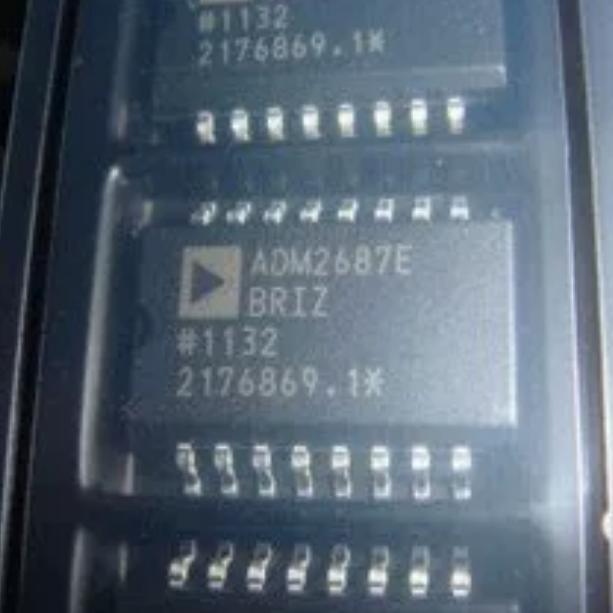
The ADM2687EBRIZ operates as a fully integrated isolated RS-485/RS-422 transceiver, combining signal isolation, power isolation, and bus transceiver functions in a single package.
Signal Isolation (iCoupler): The iCoupler digital isolation technology uses chip-scale microtransformers fabricated directly on the semiconductor die to couple digital signals across the isolation barrier. The input data signals (TxD, DE, RE) are encoded into high-frequency pulses that drive the primary windings of the microtransformers. The secondary windings receive the coupled pulses, which are decoded back to the original digital signals. The 3-channel isolator provides three independent isolation channels: one for transmit data (TxD to Y/Z), one for receive data (A/B to RxD), and one for control signals (DE and RE). The isolation barrier provides 5 kVrms galvanic isolation with common-mode transient immunity exceeding 25 kV/us.
Power Isolation (isoPower): The isoPower DC-DC converter uses high-frequency switching (approximately 180 MHz) to transfer power across chip-scale transformers from the logic side to the bus side. The converter takes the logic-side VCC supply (3.3V or 5V) and generates an isolated supply (VISOOUT) at the same nominal voltage for the bus-side transceiver circuitry. The VISOOUT pin must be externally connected to the VISOIN pin to supply power to the bus-side circuitry. This eliminates the need for an external isolated power supply, significantly simplifying system design and reducing component count. The high switching frequency enables the use of very small transformer structures that fit within the IC package, but requires careful PCB layout to control radiated emissions (refer to AN-0971).
RS-485 Transmitter: The differential line driver takes the isolated TxD signal and drives the Y (non-inverting) and Z (inverting) outputs when DE is HIGH. When DE is LOW, the driver outputs are high-impedance (tri-stated). The driver provides current-limited output with typical short-circuit current of 200mA. The differential output voltage is at least 1.5V with a 54-ohm load between Y and Z. In full-duplex mode, the Y and Z pins serve as dedicated driver outputs.
RS-485 Receiver: The differential receiver monitors the A (non-inverting) and B (inverting) input pins when RE is LOW. The receiver output (RxD) goes HIGH when (A-B) is greater than -30mV and LOW when (A-B) is less than -200mV. Between -200mV and -30mV, the output state is indeterminate. When RE is HIGH, the receiver output is tri-stated. The fail-safe biasing ensures the receiver output defaults to HIGH when the inputs are open (no connection) or shorted together, preventing reception of noise on an idle bus. In full-duplex mode, A and B serve as dedicated receiver inputs.
Half-Duplex vs Full-Duplex: The device can be configured for either mode through external pin connections. In full-duplex mode, the driver outputs (Y, Z) and receiver inputs (A, B) are connected to separate differential pairs on the bus cable (4-wire + ground). In half-duplex mode, Y is connected to A and Z is connected to B externally, sharing a single differential pair (2-wire + ground). The DE and RE pins control the direction of data flow, with the device transmitting when DE=HIGH and receiving when RE=LOW.
Thermal and Current Protection: The device includes current limiting on the driver outputs that activates when the output current exceeds approximately 200mA (short-circuit condition). A thermal shutdown circuit disables the driver when the junction temperature exceeds approximately 150C, protecting the device from damage during sustained fault conditions such as bus contention where multiple drivers are active simultaneously.





 English
  简体中文
简体中文  Español
  العربية