以下是 KDZVTR5.1B 引脚描述的详细说明,这是一种齐纳二极管 (具体来说是 SOD-123F 或类似表面贴装封装中的 5.1V 齐纳二极管)。
Given that the “KDZVTR5.1B” is a standard two-terminal semiconductor device (a Zener diode), its pin description is very simple, but crucial for correct circuit operation.
KDZVTR5.1B Pin Description (Expanded)
The device has only two pins (terminals), but they are not interchangeable in a standard circuit. Here is the detailed breakdown:
引脚编号 引脚名称 类型 描述 1 阴极(K) 功率/参考 标记端(通常是封装上的带状或线)。 这是正常齐纳工作时的负极。它必须连接到电源的正极或需要调节的电路节点。电压参考于该引脚到阳极。2 阳极(A) 接地/回流 无标记端。 这是正常齐纳工作时的正极。它通常连接到地(0V), 或者当齐纳击穿时,电路的负极电流从阴极流向阳极。
Functional Behavior (How to use it)
To understand the pins, you must understand the two operating modes of a Zener diode:
- Normal Operation (Reverse Bias / Breakdown Mode):
- The Cathode is connected to the positive voltage (e.g., +5.1V rail).
- The Anode is connected to ground (0V).
- When the voltage across the device (Cathode to Anode) exceeds 5.1V, the diode “breaks down” and conducts current to maintain a constant 5.1V drop. This is the intended use.
- Forward Bias (Not normally used):
- If the Anode is at a higher voltage than the Cathode (e.g., Cathode = 0V, Anode = +2V), the device acts like a standard silicon diode (forward voltage drop ~0.7V). It will conduct heavily, damaging the circuit or the diode itself if current is not limited.
Critical Design Considerations for these Pins
Because this is a surface-mount Zener diode, the physical pin layout and thermal behavior are important:
1. Polarity is Critical (Easy to Get Wrong)
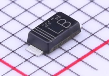
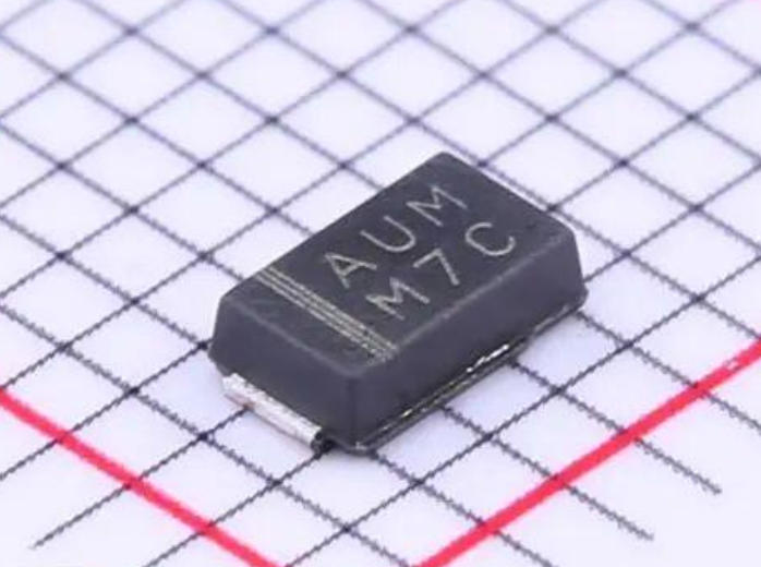
- The Cathode is almost always marked with a black band, line, or dot on the top of the SOD-123F package. The Anode is the unmarked end.
- Wrong polarity: If you reverse the pins in a voltage regulation circuit, you will essentially place a 0.7V forward-biased diode across your power rail, which will cause a short circuit and potentially destroy the diode and the power supply.
2. Thermal Path (SOD-123F Package)
- The Anode pad is typically connected to the larger portion of the internal die. In some PCB layouts, the Anode pad may have a larger copper pour or thermal via to help dissipate heat generated during Zener operation.
- The Cathode pad is often smaller.
3. Power Dissipation
- The KDZVTR5.1B is a Zener diode, so it dissipates power.
- Current flows from Cathode to Anode during regulation. The power dissipated (P = Vz * Iz) generates heat, which must be conducted away through the solder joints on both pins.
- Do not exceed the rated current. The “B” suffix may indicate a specific current rating or tolerance (e.g., 5.1V ±5%). Check the datasheet for the maximum continuous current (Izt or Izm).
4. Circuit Connection Example (Simple 5V Regulator)
- Pin 1 (Cathode): Connect to the output of a resistor or current source (which is connected to a higher voltage, e.g., 9V).
- Pin 2 (Anode): Connect to Ground (0V) .
- Voltage at Cathode: ~5.1V relative to ground.
摘要表(快速参考)
引脚名称表示电压(调节) 电流流 1 阴极(K)能带/线路, 进入二极管 2 阳极(A),无更多负极(GND) 从二极管输出 。
Key Takeaway: The KDZVTR5.1B is a simple but polarity-sensitive device. The Cathode is the marked, positive reference pin (for regulation), and the Anode is the unmarked, ground return pin. Never reverse them in a circuit expecting regulation.





 English
  简体中文
简体中文  Español
  العربية