
Electronic components are the basic units of electronic circuits, covering all electrical elements and devices. They are essential for building electronic equipment and realizing various specific functions, with core capabilities including energy conversion, signal processing, and circuit protection. Common types include resistors, capacitors, inductors, diodes, transistors, and integrated circuits.
1. Basic Passive Components
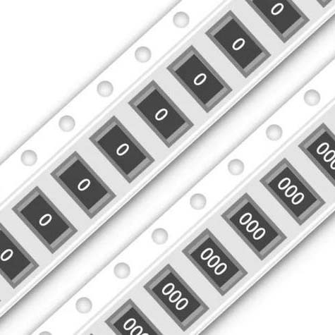
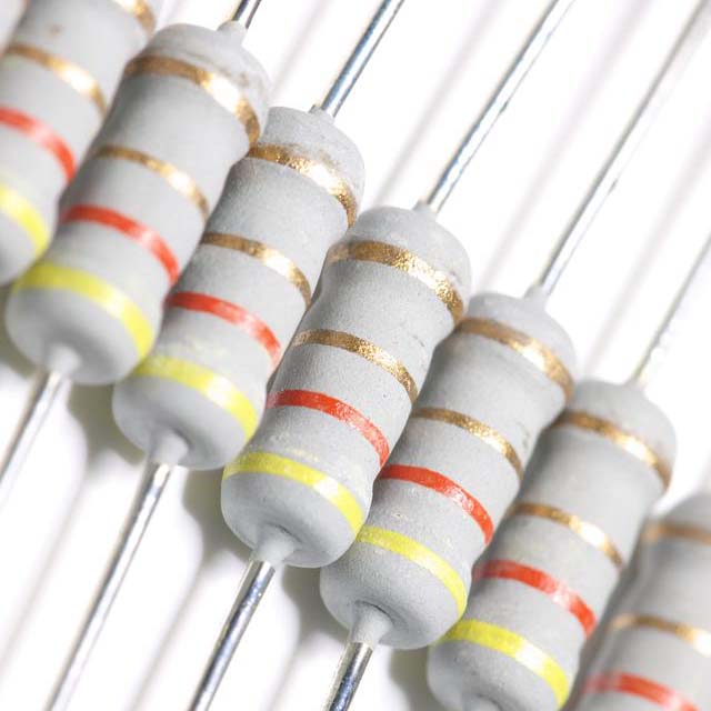
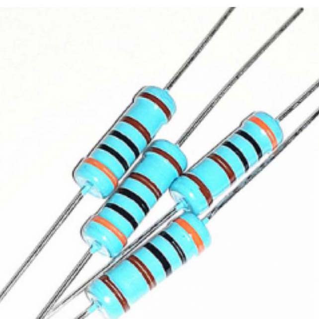
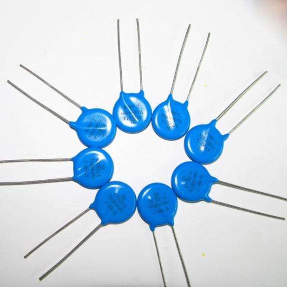
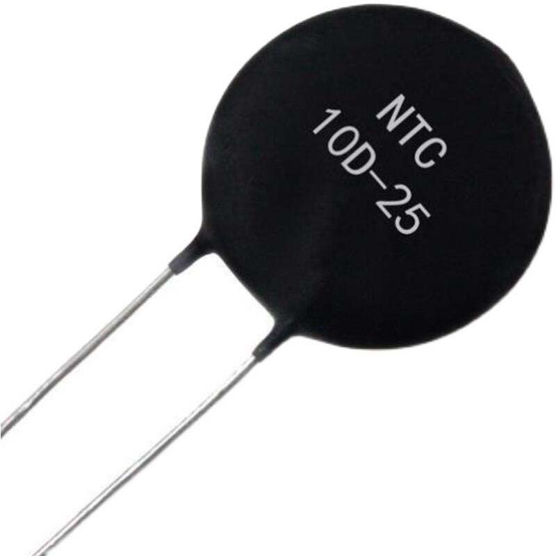
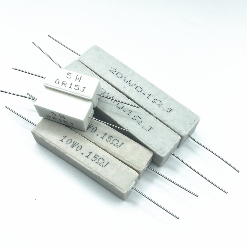
1.1 Resistor (Symbol: R)
A resistor is a passive component that impedes the flow of electric current in a circuit. Its resistance value is defined by the ratio of the voltage (U) across a conductor to the current (I) passing through it, following the formula: R=U/I. A higher resistance value means a stronger blocking effect on current.
1.1.1 Unit Conversion
The basic unit of resistance is Ohm (Ω). The standard conversion rules are as follows:
- 1 kiloohm (kΩ) = 10³ Ω
- 1 megaohm (MΩ) = 10⁶ kΩ = 10⁶ Ω
1.1.2 Resistance Value Marking Methods
Resistance parameters (nominal resistance value and tolerance) are mainly marked in four ways for circuit identification:
- Direct Marking Method: Directly print the resistance value, power rating, and tolerance on the resistor body, mostly applied to high-power resistors.
- Color Band Marking Method: The most common marking for conventional resistors. For 4-band resistors, the first two bands represent valid resistance values, the third represents the multiplier, and the fourth represents the tolerance. 5-band precision resistors adopt three valid value bands for higher accuracy, with the last band reserved for tolerance. Color band resistors are available in 3-band, 4-band, 5-band and 6-band types, among which 4-band resistors are the most widely used.
- Text Symbol Method: Use combinations of numbers and letters for simplified marking (R, K, M act as decimal points). Resistors without tolerance marking have a default tolerance of ±20%. Typical examples: 6R8 = 6.8Ω, 33R = 33Ω, 3Ω3 = 3.3Ω (±5% tolerance), 1K8 = 1.8kΩ (±20% tolerance), 5M1 = 5.1MΩ (±10% tolerance).
- Digital Code Method: Adopt three-digit codes for nominal value marking (commonly used for SMD resistors). The first two digits are valid values, and the third digit indicates the number of trailing zeros. Tolerance is usually marked with letters. Typical examples: 101 = 100Ω, 153 = 15kΩ, 102 = 1kΩ, 103 = 10kΩ, 104 = 100kΩ, 105 = 1MΩ.
1.1.3 Resistor Classification and Characteristics
Resistors are divided into fixed resistors and variable resistors according to adjustability of resistance value, and can be further classified by material, application, structural form and special functions.
Fixed Resistors: With unadjustable and fixed resistance values, including the following mainstream types:
- Carbon Film Resistor: Small in size, low in cost, suitable for ordinary general circuits with low performance requirements.
- Metal Film Resistor: High precision and stability, low temperature drift, widely used in precision instruments and measuring equipment.
- Metal Oxide Film (MOX) Resistor: Excellent power bearing capacity and temperature stability, applicable to high-power circuits and high-temperature working environments.
Variable Resistors: With adjustable resistance values via knobs, sliding structures or digital programming:
- Knob-type variable resistors: Adjust resistance manually, used for volume and brightness control.
- Sliding variable resistors: Realize stepless resistance adjustment, applied to light regulation and motor speed control.
- Programmable resistors: Adjust resistance through digital signals or programming, suitable for automatic control and digital circuits.
The detailed classification, features and applications of common resistors are summarized in the table below:
| Classification Dimension | Resistor Type | Core Features | Aplicaciones típicas |
| By Material | Carbon Film Resistor | Low cost, ordinary stability and low precision | Ordinary low-demand electronic circuits |
| Metal Film Resistor | High precision (±1%~±5%), low temperature coefficient, low noise | Precision instruments, communication equipment | |
| Metal Oxide Film Resistor | High temperature resistance, high power tolerance, excellent oxidation resistance | High-power power supply circuits, high-temperature working scenarios | |
| Wire-wound Resistor | High power tolerance, high temperature resistance, high precision, poor high-frequency performance | High-power load circuits, current limiting scenarios | |
| Resistencia SMD | Ultra-small size, suitable for automated mass production | Smartphones, computers and compact modern electronic devices | |
| By Purpose | Ordinary Resistor | General performance, wide applicability | Current limiting, voltage division and load of common circuits |
| Precision Resistor | Precision up to ±0.1% or higher, excellent temperature stability | Measuring instruments, high-precision ADC/DAC circuits | |
| Resistencia de potencia | High power tolerance (several watts to hundreds of watts), good heat dissipation | Power supply systems, motor control circuits | |
| Sensitive Resistor | Resistance changes with external physical parameters (temperature, light, voltage, humidity) | Environmental detection, circuit protection and sensing systems | |
| By Structural Form | Through-hole Resistor / SMD Resistor / Integrated Resistor Network | Through-hole type for manual welding; SMD type for high-density circuits; network type with multiple integrated resistors | Conventional PCB welding, miniaturized circuit design, modular circuit wiring |
| Special Types | Fuse Resistor / Zero-Ohm Resistor / High-Voltage Resistor | Fuse type integrates resistance and fuse functions; zero-ohm type acts as jumper; high-voltage type withstands kilovolt-level voltage | Circuit overcurrent protection, PCB wiring jumpers and testing, high-voltage equipment circuits |
1.1.4 Core Applications of Resistors
- Current Limiting & Circuit Protection: Connect fixed resistors (e.g., 220Ω) in series with LEDs to prevent burnout caused by excessive current; adopt small-resistance resistors (e.g., 0.1Ω) at power output terminals for overcurrent detection, cooperating with fuses to realize circuit protection.
- Voltage Division & Signal Regulation: Use potentiometers to adjust the output signal amplitude of photoelectric and thermosensitive sensors, adapting signals to the input voltage range of ADC modules; control audio volume and light brightness by adjusting voltage division ratios.
- Power Regulation: Connect power resistors in series with DC motors to consume excess power and adjust motor speed; apply variable resistors to electric heating equipment to control heating power and temperature.
- Signal Processing & Filtering: Use 50Ω resistors for impedance matching in RF circuits to reduce signal reflection and improve transmission efficiency; form RC low-pass filter circuits to filter high-frequency noise and retain effective low-frequency signals.
- Calibration & Circuit Optimization: Adopt high-precision metal film resistors inside precision instruments such as multimeters to calibrate measurement benchmarks; use adjustable resistors to optimize oscillator frequency and operational amplifier gain.
- Special Functional Protection & Wiring: Parallel varistors at AC power input terminals to absorb surge voltage and protect post-stage circuits; apply NTC thermistors for temperature detection in air conditioners and other equipment; use zero-ohm resistors as PCB jumpers to simplify wiring and facilitate circuit testing and version iteration.
1.2 Capacitor (Symbol: C)
A capacitor is a basic linear passive component that stores electric charge and electric energy. Its capacitance is defined as the ratio of stored charge (Q) to potential difference (U), following the formula: C=Q/U. With unique charging and discharging characteristics, capacitors are widely used in circuit filtering, signal coupling, energy storage, timing, DC blocking and power compensation scenarios.
1.2.1 Unit Conversion & Digital Coding Rules
The basic unit of capacitance is Farad (F), with standard subdivisions and conversion relations as follows:
1F = 10³mF = 10⁶μF = 10⁹nF = 10¹²pF
SMD capacitors generally adopt three-digit digital coding (unit: pF): the first two digits are valid values, and the third digit represents the number of trailing zeros. Typical examples: 101=10pF, 102=100pF=1nF, 103=1000pF=10nF, 104=100000pF=100nF, 105=1μF, 106=10μF, 107=100μF.
1.2.2 Working Principle
A capacitor consists of two conductive plates and an insulating dielectric sandwiched between them. When powered on, charges accumulate on the plate surfaces to store electric energy; when the circuit discharges, the stored energy is released to supply power for the circuit. The capacitance of a parallel-plate capacitor follows the formula C=ϵS/d, determined by the dielectric constant (ϵ), plate facing area (S) and plate spacing (d).
1.2.3 Core Applications of Capacitors
- Energy Storage & Instant Power Supply: Realize rapid charging and discharging to provide instantaneous high-power output. Typical applications include camera flash power supply and electric vehicle regenerative braking energy storage, which recycles motor feedback power during braking for subsequent acceleration.
- Voltage Filtering & Stabilization: Absorb AC ripples in DC power supplies and stabilize operating voltage. Electrolytic capacitors are used in power adapters to ensure stable charging voltage; multiple ceramic capacitors are arranged near CPU power pins on motherboards to filter high-frequency interference and prevent system crashes.
- DC Blocking & AC Coupling: Block DC static voltage and transmit AC signals without distortion. Widely applied to audio amplifiers (isolating DC bias and transmitting audio signals) and RF communication modules (ensuring stable antenna matching).
- Local Decoupling & Noise Suppression: Provide local energy reserve for chips and suppress voltage fluctuations. 0.1μF ceramic capacitors are closely attached to MCU and other digital IC power pins to absorb switching noise and avoid logic errors, optimizing the power supply stability of high-speed PCB circuits.
- Timing & Oscillation: Cooperate with resistors or inductors to form RC/LC timing circuits, controlling circuit time constants and oscillation frequencies. Used for adjusting LED flashing frequency in 555 timer circuits and matching load capacitance of crystal oscillators to stabilize single-chip microcomputer clock signals.
- Power Factor Correction (PFC): Improve the phase difference between voltage and current in AC circuits to enhance energy efficiency. Large-capacity film capacitors are used in industrial frequency converters to compensate reactive power; X2 safety capacitors are applied to LED drive power supplies for energy saving and loss reduction.
- Signal Filtering & Frequency Selection: Form high-pass and low-pass filter circuits with inductors to separate high and low-frequency signals, used for speaker frequency division and radio tuning (adjusting LC resonance frequency to realize station selection).
- Voltage Buffering & Component Protection: Absorb voltage spikes and surge pulses. Parallel capacitors at relay contacts eliminate switching sparks and extend service life; buffer capacitors suppress voltage surges during the shutdown of IGBT power devices.
- Smart Sensing & Energy Harvesting: Detect physical changes through capacitance variation. Smartphone touch screens sense finger proximity via capacitance changes; supercapacitors store tiny energy collected by solar panels to power IoT devices.
- Emergency Power Supply: Supercapacitors feature high capacity and ultra-fast charging and discharging, replacing batteries for short-term power supply. They are used for bus start-stop energy saving and temporary power supply for motherboard RAM to prevent data loss.
1.3 Inductor (Symbol: L)
An inductor is a magnetic energy storage component wound with conductive coils. It converts electric energy into magnetic energy for storage when current passes through, and releases magnetic energy to maintain current stability when the current changes. Its basic unit is Henry (H).
1.3.1 Unit Conversion
1H = 10³mH = 10⁶μH = 10⁹nH
1.3.2 Classification & Core Functions
Inductors are divided into two core types according to working principles:
- Self-inductor: A single independent coil, used for single-circuit energy storage, medium and low-frequency filtering, and signal impedance matching.
- Mutual Inductor / Transformer: Composed of two matched coils. The magnetic field change of one coil induces potential in the other, realizing cross-circuit energy and signal transmission, voltage step-up/step-down and impedance conversion.
Core application scenarios of inductors include power supply high-frequency noise filtering, circuit signal coupling and voltage transformation, oscillation circuit timing control, and magnetic induction physical parameter detection.
1.3.3 Difference Between Inductor and Magnetic Bead
Both inductors and magnetic beads are used for circuit anti-interference, but with essential working mechanism and application differences:
- Working Mechanism: The inductor is an energy storage component that realizes mutual conversion between electric energy and magnetic energy; the magnetic bead is an energy consumption component that converts high-frequency electric energy into heat energy for dissipation, with cleaner filtering effect.
- Application Scenarios: Inductors are mainly used for medium and low-frequency LC filtering of power supply terminals and circuit impedance matching, suppressing conductive interference. Magnetic beads are specially used for signal circuits and EMC anti-interference, absorbing ultra-high-frequency radiation interference, widely applied in RF circuits, PLL oscillation circuits and high-speed memory circuits.
- Usage Habit: Magnetic beads are commonly used for isolation and anti-interference at the junction of analog ground and digital ground, as well as for high-precision signal line protection.
1.4 Crystal Oscillator
Conventional LC oscillation circuits suffer from poor stability and severe frequency drift. A crystal oscillator is a high-precision frequency component made of quartz crystal, which can generate ultra-stable AC signals with almost no frequency deviation. It serves as the core timing component of all intelligent electronic devices, providing stable reference clock frequency for single-chip microcomputers, CPUs, communication equipment and precision instruments.
2. Semiconductor Active Components
Different from passive components, active semiconductor components rely on external power supply to work, with core active control functions such as signal amplification, circuit switching and voltage/current regulation, which are the core carriers of intelligent circuit operation and signal processing.
2.1 Diode (Symbol: D)
A diode is a two-terminal unidirectional conductive semiconductor component, consisting of an anode and a cathode. It conducts current under forward bias voltage and cuts off completely under reverse bias voltage, equivalent to an automatic controllable circuit switch. It can cooperate with resistors, capacitors, inductors and other components to realize rectification, detection, voltage clamping, stabilization and other circuit functions.
2.1.1 Common Diode Types and Features
- Rectifier Diode: The most common diode type, used for converting AC to DC. Typical models: 1N4001-1N4007, widely used in power rectification circuits.
- Schottky Diode: Features ultra-low forward voltage drop (0.15V-0.45V) and fast switching speed, suitable for high-frequency rectification and high-speed signal processing. Typical models: 1N5819, SS14F.
- Fast Recovery Diode: Short reverse recovery time, applicable to high-frequency circuits such as switching power supplies and PWM converters. Typical models: FR107, ES1J.
- Zener Diode (Voltage Regulator Diode): Maintains stable fixed voltage under reverse breakdown state, specially used for circuit voltage regulation and reference voltage stabilization. Typical models: ZMM5V1, ZM4733.
- LED (Light Emitting Diode): Converts electric energy directly into light energy. The luminous color depends on semiconductor materials, with a forward voltage of 1.8V-3.3V. Widely used for equipment indication, lighting and display screens.
- Photodiode: Works under reverse voltage, converting optical signals into electrical signals, mainly used for light detection and optical sensor systems.
- TVS Diode (Transient Voltage Suppressor): Absorbs instantaneous surge high voltage to protect precision circuits from high-voltage impact and damage, applied to power supply and communication interface protection.
- Switching Diode: Ultra-fast on-off response, suitable for high-frequency and ultra-high-frequency digital logic circuits. Typical model: 1N4148, BAV99.
- Varactor Diode: Utilizes the characteristic that PN junction capacitance changes with reverse bias voltage, used for circuit frequency modulation and radio tuning.
- ESD Diode: Specialized in electrostatic discharge protection to prevent circuit damage caused by static electricity.
2.1.2 Core Applications of Diodes
Diodes cover multiple key circuit functions: AC-DC rectification for power conversion; overvoltage and reverse-connection protection for circuit safety; high-frequency signal demodulation for communication and audio equipment; LED light indication and lighting; voltage clamping and multiplication for signal amplitude control; freewheeling protection for inductive loads such as coils; and signal conditioning and power management for industrial automation and communication equipment.
2.2 Transistor
The transistor is the core amplification and switching component of electronic circuits. Two adjacent PN junctions are fabricated on a semiconductor substrate, dividing the substrate into three regions: emitter, base and collector. It is divided into NPN and PNP types. It realizes precise control of large current signals through tiny base current, completing signal amplification and circuit on-off control.
2.2.1 Core Working Parameters
- Maximum Collector Current (IC max): The maximum sustainable current of the transistor; exceeding the limit will cause overheating and damage.
- Maximum Collector-Base Voltage (VCE max): The maximum withstand voltage of the transistor; overvoltage will lead to PN junction breakdown.
- Maximum Power Dissipation (P max): The maximum sustainable power consumption; excessive power causes thermal burnout.
- Current Gain (β): Represents the signal amplification multiple, reflecting the transistor’s amplification capability.
2.2.2 Core Functions and Application Scenarios
- Signal Amplification: Amplify weak audio, sensor and RF signals, serving as the core of all amplifier circuits, widely used in audio equipment and communication systems.
- Electronic Switch: Realize circuit on-off through saturation conduction and cut-off states, the basic component of digital logic circuits, computers and memory systems.
- Circuit Control: Used for voltage stabilization, constant current source output, oscillation signal generation, frequency multiplication and signal limiting, applicable to power regulation and timing control circuits.
2.3 Thyristor (SCR)
Also known as silicon controlled rectifier, the thyristor is a high-power semiconductor component with the advantages of small size, high efficiency and long service life. It can control high-power equipment with tiny control signals, realizing low-power control of high-power circuits. It is divided into unidirectional thyristors and bidirectional thyristors (TRIAC). Bidirectional thyristors are equivalent to two reverse-connected unidirectional thyristors, featuring bidirectional conduction function, simple control circuit and no reverse withstand voltage problem, especially suitable for AC non-contact switch scenarios. It is widely used in AC motor speed regulation, power regulation and industrial automatic control systems.
3. Integrated Circuits and Functional Modules
3.1 Integrated Circuit (IC)
An integrated circuit integrates thousands of discrete components such as transistors, resistors and capacitors and internal wiring on a tiny semiconductor chip, packaged into a miniature component with complete independent circuit functions. It realizes the miniaturization, high integration and high stability of electronic systems.
3.1.1 Classification of Integrated Circuits
- By Signal Type: Analog ICs (process continuous analog signals), digital ICs (process discrete logic signals), mixed-signal ICs (compatible with both analog and digital signals).
- By Integration Scale: SSIC (small-scale), MSIC (medium-scale), LSIC (large-scale), VLSIC (very large-scale), ULSIC (ultra-large-scale), GSIC (giant-scale).
- By Conductive Type: Bipolar ICs (complex process, high power consumption, e.g., TTL, ECL series) and unipolar ICs (simple process, low power consumption, easy for large-scale integration, e.g., CMOS, NMOS, PMOS series).
- By Purpose: General-purpose ICs and special-purpose ICs for televisions, audio equipment, computers, communication devices and industrial alarms.
3.1.2 Common Packaging Forms and Characteristics
- DIP (Dual In-line Package): Dual-row pin layout, suitable for through-hole welding with simple operation; large volume, low integration, applied to early CPUs and small and medium-scale ICs.
- QFP (Quad Flat Package): Dense fine pins, compatible with SMT surface mounting technology, excellent high-frequency performance, used for large-scale integrated circuits.
- BGA (Ball Grid Array): Spherical solder joints at the bottom, high pin density, excellent heat dissipation, solving high-frequency signal interference problems, widely used in modern CPUs, GPUs and high-performance chips.
The mainstream development trends of IC packaging include high-density CSP chip-scale packaging and 3D stacked packaging, which greatly improve chip integration and miniaturization, and shorten signal transmission paths.
3.2 Sensor
A sensor is a core detection device of intelligent electronic systems. It senses physical, chemical or biological information of the external environment and converts it into standard electrical signals according to fixed rules, realizing signal transmission, processing, monitoring and control. According to sensitive mechanisms, sensors are divided into physical sensors (based on force, heat, light, magnetism and acoustic effects), chemical sensors (based on chemical reactions) and biosensors (based on molecular recognition). They are widely used in industrial monitoring, intelligent detection and IoT equipment.
3.3 Relay & Transformer
- Relay: A special power control electrical component. It can expand circuit control range, realize signal amplification and multi-circuit synchronous switching with tiny control signals, and support automatic control and remote monitoring of strong and weak electricity isolation circuits, which is the key component of automatic control systems.
- Transformer: A power conversion device based on electromagnetic mutual induction principle, composed of primary coil, secondary coil and iron core. Its core functions include AC voltage step-up/step-down, current conversion, impedance matching and circuit electrical isolation, widely used in power transmission, wireless circuits and electrical equipment.
4. Summary
Electronic components are the fundamental cornerstone of all electronic equipment and electronic technology innovation. Passive components including resistors, capacitors and inductors undertake basic circuit stabilization, filtering, energy storage and signal regulation functions; semiconductor active components such as diodes, transistors and thyristors realize core signal amplification, switching and circuit control; integrated circuits and functional sensors, relays and transformers complete system-level intelligent processing, power conversion and automatic control. Mastering the basic principles, classification characteristics and practical application scenarios of mainstream electronic components is the essential foundation for electronic circuit design, equipment maintenance and electronic technology innovative development.
 English
  简体中文
简体中文  Español
  العربية